A voltage divider looks innocent. Two resistors, one input, one output, and a formula so friendly it practically waves at beginners: output voltage equals input voltage multiplied by a resistor ratio. Then a capacitor strolls into the circuit, and suddenly this “simple divider” starts caring about frequency. Low frequencies get one treatment, high frequencies get another, and your humble divider has quietly become a filter. Electronics: where even the small parts have double lives.
The title “Voltage Divider? Filter? It’s Both!” captures one of the most useful ideas in analog electronics: many filters are just voltage dividers with frequency-dependent impedance. Replace one resistor with a capacitor, add a capacitor across one leg, or include parasitic capacitance you did not invite to the party, and the divider no longer divides the same way at every frequency. That can be exactly what you want, or exactly why your circuit behaves like it has been drinking espresso.
In this guide, we will unpack how a voltage divider becomes an RC filter, why capacitive reactance is the secret ingredient, how to calculate cutoff frequency, and where this idea shows up in real circuits such as sensor inputs, audio paths, power-supply feedback networks, ADC front ends, and oscilloscope probes.
What Is a Voltage Divider?
A basic voltage divider uses two series resistors to create a smaller output voltage from a larger input voltage. The output is usually taken across the lower resistor. In its classic DC form, the formula is:
For example, if R1 is 10 kΩ and R2 is 10 kΩ, the output is half the input. Feed it 5 V, and you get about 2.5 V at the output, assuming the load connected to the output has very high input impedance. That last phrase matters. A voltage divider is not a magical power supply; it is a ratio-making network. If you attach a load that draws significant current, the load effectively changes the lower leg resistance, and your neat math starts wearing clown shoes.
Voltage dividers are commonly used to scale signals for microcontrollers, create reference voltages, bias transistor stages, read variable sensors, and set feedback levels in power supplies. They are simple, cheap, predictable at DC, and easy to build. But the moment capacitance or inductance becomes important, the divider’s ratio can change with frequency.
The Missing Ingredient: Impedance
Resistance is steady in the ideal world. A 10 kΩ resistor is 10 kΩ whether the signal wiggles slowly or quickly. Capacitors and inductors are different. Their opposition to AC signals is called reactance, and reactance depends on frequency.
For a capacitor, capacitive reactance is:
That formula says something wonderfully important: as frequency increases, capacitive reactance decreases. At DC, where frequency is zero, an ideal capacitor behaves like an open circuit. At high frequencies, it begins acting more like a low-impedance path. In less formal terms, a capacitor ignores slow changes but gets very interested when signals start moving fast.
This is the bridge between a voltage divider and a filter. If one leg of the divider changes impedance with frequency, the output voltage also changes with frequency. Congratulations, you now have a frequency-selective circuit.
How a Divider Becomes a Low-Pass Filter
The classic RC low-pass filter places a resistor in series with the input and a capacitor from the output node to ground. The output is taken across the capacitor. At low frequencies, the capacitor has high reactance, so very little signal is shunted to ground. The output remains close to the input. At high frequencies, the capacitor’s reactance drops, giving those fast signal components an easier path to ground. The output becomes smaller.
That is why the circuit is called a low-pass filter: it passes low-frequency content and attenuates high-frequency content. It is also a voltage divider because the output is determined by the ratio between the resistor and the capacitor’s frequency-dependent impedance.
Low-Pass Example
Suppose you use a 10 kΩ resistor and a 0.1 µF capacitor. The cutoff frequency is:
Plugging in the numbers:
Below about 159 Hz, the circuit passes signals with relatively little attenuation. Above that point, the output begins rolling off. For a first-order RC filter, the slope is about -20 dB per decade after the cutoff frequency. In everyday language: increase the frequency by ten times, and the signal gets much smaller.
This kind of filter is useful for smoothing sensor readings, reducing high-frequency noise, cleaning up audio signals, and keeping ADC inputs from sampling unwanted fast noise. It is small enough to fit almost anywhere and cheap enough that designers use it constantly.
How a Divider Becomes a High-Pass Filter
Now swap the positions. Put the capacitor in series with the input and the resistor from the output node to ground. Take the output across the resistor. At low frequencies, the capacitor’s reactance is high, so little signal reaches the output. At high frequencies, the capacitor’s reactance becomes low, allowing the signal to pass through to the resistor.
This is a high-pass filter. It blocks DC and slow variations while passing faster changes. Again, it is still a voltage divider. The only difference is that the frequency-dependent component is now in the series leg instead of the shunt leg.
High-pass filters are used for AC coupling, removing DC offset, detecting edges, and keeping slow baseline drift out of signal chains. In audio, for example, a coupling capacitor can remove unwanted DC while allowing the music signal to continue. Your speakers appreciate not being fed a DC workout routine.
The Cutoff Frequency: Where the Divider Changes Its Mind
The cutoff frequency, often written as fc, is the point where the output magnitude has dropped to about 70.7% of the input, or -3 dB. It does not mean the signal suddenly disappears. Filters are not brick walls unless you build far more complicated ones. A first-order RC filter is more like a polite hill: gradual, predictable, and usually good enough for a surprising number of jobs.
The same cutoff equation applies to simple RC low-pass and high-pass filters:
Choosing R and C is therefore a design decision. A larger resistor or capacitor lowers the cutoff frequency. A smaller resistor or capacitor raises it. If you are filtering a slow temperature sensor, a low cutoff frequency may be fine. If you are conditioning an audio signal, you need to choose values carefully so you do not accidentally turn the bass line into a rumor.
When a Plain Resistor Divider Also Becomes a Filter
A two-resistor divider can become a filter even if you did not intentionally add a capacitor. Real circuits contain parasitic capacitance. PCB traces have capacitance. Input pins have capacitance. Oscilloscope probes have capacitance. Cables have capacitance. The universe, apparently, enjoys hiding tiny capacitors everywhere.
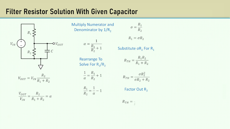
Imagine a voltage divider made from R1 and R2, with the output node connected to a device input that has capacitance to ground. At DC, the divider ratio is still approximately R2 divided by R1 plus R2. But at higher frequencies, that capacitance provides an additional path to ground. The output node starts behaving like a low-pass filter.
For a divider with a capacitor across the lower resistor, the effective resistance that works with the capacitor is often the Thevenin resistance of the divider, which is R1 in parallel with R2. The time constant becomes:
That detail is easy to miss. If you only use R2 in your cutoff estimate, your calculation may be off. The capacitor “sees” the resistance looking back into the divider, and that resistance is the parallel combination of the two divider resistors when the source is treated as AC ground.
Practical Example: Scaling a 12 V Signal for a 3.3 V ADC
Suppose you want to measure a 12 V battery with a 3.3 V microcontroller ADC. You might choose R1 = 100 kΩ and R2 = 33 kΩ. The DC output is:
That keeps the ADC input safely below 3.3 V. Now add a 100 nF capacitor from the ADC input to ground to reduce noise. The divider is no longer only a divider; it is a low-pass filter too.
The effective resistance is:
The cutoff frequency is:
This is great for a slowly changing battery voltage. It reduces high-frequency noise before the ADC reads the signal. But if you were trying to measure a fast-changing waveform, this same filter would smear out the details. One circuit, two personalities: helpful assistant or signal-squashing gremlin, depending on the job.
Why Loading Matters
A voltage divider assumes the output is not heavily loaded. When you connect another circuit, that circuit’s input impedance becomes part of the divider. If the input impedance is extremely high compared with the divider resistors, the effect is small. If it is comparable, the output voltage shifts.
With filters, loading also changes the cutoff frequency and response shape. A passive RC filter feeding a low-impedance load may not behave like the textbook version. The load can appear in parallel with the capacitor or resistor, changing the effective impedance. This is why buffer amplifiers are often used when accuracy matters. An op-amp buffer can isolate the divider or filter from the next stage, allowing the RC network to behave more predictably.
Where This “Both” Circuit Shows Up
Sensor Inputs
Sensor signals are often noisy, especially in environments with motors, switching power supplies, long wires, or radio-frequency interference. A resistor divider may scale the signal, while a capacitor to ground filters high-frequency noise before it reaches an ADC. This is common in battery monitors, thermistor circuits, pressure sensors, and industrial analog inputs.
Power-Supply Feedback
Switching regulators use feedback dividers to set output voltage. Because the feedback node can be sensitive and high impedance, layout matters. Designers often keep the divider close to the regulator feedback pin and route the node carefully to reduce injected noise. In some designs, small capacitors are added to shape transient response or filter noise. The divider is not just setting voltage; it is participating in the control loop’s frequency behavior.
Audio Coupling
A capacitor in series with an audio input and a resistor to ground forms a high-pass filter. It removes DC offset while letting the audible AC signal through. Choose the cutoff too high, and your audio loses bass. Choose it too low, and the circuit may take longer to settle after power-up. The math is small, but the consequences can be heard.
Oscilloscope Probes
A 10:1 oscilloscope probe is a carefully compensated voltage divider. It must divide voltage accurately across a wide frequency range. If the probe capacitance is not properly compensated, square waves look rounded, peaked, or otherwise suspicious. That little adjustment screw on a passive probe is not decoration; it is there to balance resistive and capacitive divider behavior so measurements stay accurate.
Anti-Aliasing Before ADCs
Before an analog-to-digital converter samples a signal, high-frequency content can fold into the measured band as aliasing. A simple RC low-pass filter can reduce unwanted high-frequency components before sampling. It is not always enough for demanding systems, but for many embedded projects, it is an excellent first layer of defense.
Design Tips for RC Divider-Filters
1. Start With the Signal
Ask what you want to preserve. If your useful signal changes slowly, a lower cutoff frequency may be beneficial. If your useful signal contains fast edges or high-frequency information, do not filter it away in the name of “cleaning things up.” Clean is good. Missing is not.
2. Watch Source and Load Impedance
The resistor values you choose affect current draw, noise, settling time, and loading. Very large resistors save power but make the circuit more sensitive to leakage current, input capacitance, and noise pickup. Very small resistors reduce impedance problems but waste more current. Engineering is mostly choosing which problem you prefer.
3. Remember ADC Sampling Behavior
Microcontroller ADC inputs often include a small internal sample-and-hold capacitor. If your divider resistance is too high, the ADC may not charge that internal capacitor quickly enough, causing inaccurate readings. A capacitor at the ADC pin can help by acting as a local charge reservoir, but it also forms a low-pass filter with the divider resistance.
4. Simulate Before You Solder
Tools such as LTspice make it easy to run AC analysis and view magnitude and phase response. A quick simulation can reveal whether your “simple” filter rolls off where you expect, whether the phase shift matters, and whether the load changes the result. Simulations are not a replacement for measurement, but they are cheaper than repeatedly desoldering parts while questioning your life choices.
5. Measure Carefully
Measurement tools affect circuits. A scope probe adds resistance and capacitance. A multimeter adds input resistance. Long ground leads can introduce inductance and noise. If a circuit changes behavior when you probe it, that does not mean it is haunted. It means your measuring instrument has joined the circuit.
Common Mistakes
Using a Divider as a Power Supply
A resistor divider is usually a poor way to power a load. The output voltage depends heavily on load current, and power is wasted in the resistors. Use a regulator, DC-DC converter, or proper reference source when current demand matters.
Ignoring Capacitor Tolerance
Capacitors can have wide tolerances, especially ceramic capacitors with certain dielectrics. A nominal 0.1 µF capacitor may not behave exactly like 0.1 µF under voltage, temperature, and frequency conditions. For rough filtering, that may be acceptable. For precision filters, choose components more carefully.
Forgetting Phase Shift
Filters do not only change amplitude; they also shift phase. In control loops, audio crossovers, communication circuits, and feedback systems, phase shift can matter a lot. A single-pole RC filter introduces up to 90 degrees of phase shift across its transition region.
Placing Components Poorly
A filter capacitor should usually be close to the node it is filtering. Long traces add resistance, inductance, and opportunities for noise pickup. In high-impedance divider networks, layout can make the difference between a clean reading and a tiny antenna auditioning for a radio station.
Experience Notes: What This Circuit Teaches in the Real World
The first time many people meet the “voltage divider and filter at the same time” idea, it is not in a textbook. It is usually on a breadboard, late at night, when a sensor reading refuses to sit still. You build a divider to scale a voltage into a microcontroller. The math checks out. The wiring looks correct. The serial monitor, however, behaves like it is reporting the emotional state of a squirrel. Then someone suggests adding a capacitor from the ADC input to ground. Suddenly the readings calm down. The divider did not stop being a divider; it gained a second job as a low-pass filter.
That moment is valuable because it turns theory into instinct. You begin to see every node as having resistance, capacitance, and frequency behavior. A long wire is no longer “just a wire.” A high-value resistor divider is no longer “just two resistors.” A microcontroller input is no longer an infinite-impedance fairy tale. Everything interacts. That can sound intimidating, but it is also what makes electronics fun. Circuits are conversations between parts, and sometimes the capacitor is the one quietly changing the subject.
In practical projects, this lesson shows up constantly. A battery monitor for a solar charger may use large resistor values to reduce current drain, then add a capacitor so the ADC sees a stable voltage. A guitar pedal may use coupling capacitors and bias resistors that form high-pass filters, shaping tone before any obvious “tone control” appears. A power-supply feedback divider may need careful placement because switching noise can couple into the feedback pin. A scope probe may display a distorted square wave until its compensation capacitor is adjusted. Each case is a version of the same story: voltage division and filtering are not separate kingdoms. They share a border.
One of the best habits is to calculate twice: once for DC and once for AC. For DC, ask what the divider ratio is. For AC, ask what capacitances exist and what resistance they see. If you added a capacitor intentionally, calculate the cutoff frequency. If you did not add one, consider whether input capacitance, cable capacitance, or probe capacitance is doing the job behind your back. This simple habit catches many “mystery” problems before they become long debugging sessions powered by coffee and regret.
Another useful experience is to test with a square wave. A square wave contains many frequency components, so it quickly reveals whether a circuit is rounding edges, overshooting, or attenuating high-frequency content. A divider that looks perfect with a DC multimeter may look very different on an oscilloscope when driven by a fast signal. That does not mean the divider is bad. It means it has frequency response, like every real circuit.
The practical takeaway is simple: when you place resistors and capacitors together, you are not only setting voltages. You are shaping time, frequency, noise, settling, and measurement behavior. A voltage divider can be a filter. A filter can be analyzed as a divider. Once that clicks, analog circuits become far less mysteriousand much more interesting.
Conclusion
A voltage divider and an RC filter are not distant relatives; they are often the same circuit viewed from different angles. A resistor divider sets a voltage ratio at DC. Add a capacitor, replace one resistor with a reactive component, or account for unavoidable parasitic capacitance, and the ratio becomes frequency dependent. That is filtering.
The most important idea is that impedance changes the divider ratio. Capacitors have high reactance at low frequencies and low reactance at high frequencies, which allows RC networks to behave as low-pass or high-pass filters depending on where the output is taken. This principle explains sensor smoothing, ADC input filtering, audio coupling, oscilloscope probe compensation, power-supply feedback behavior, and many other everyday electronics decisions.
So the next time you see two resistors and a capacitor, do not ask whether it is a voltage divider or a filter. Smile knowingly, adjust your imaginary lab coat, and say: “Yes.”
Note: This article is written for educational and web publishing purposes. Always verify component values, voltage ratings, tolerances, ADC requirements, and safety limits for your specific circuit before building or connecting hardware.