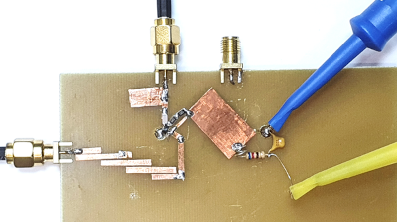
A microwave frequency doubler sounds like a tiny magic trick for engineers: feed it one frequency, and it politely hands back another frequency that is exactly twice as high. No wand, no cape, no dramatic smoke machinejust nonlinear physics, careful impedance matching, filters, and a healthy respect for parasitic capacitance. In RF and microwave systems, that little trick is extremely useful. A frequency doubler can turn a clean 5 GHz signal into 10 GHz, a 12 GHz source into 24 GHz, or a millimeter-wave local oscillator chain into something that makes test equipment feel like it just joined a gym.
In simple terms, a microwave frequency doubler is a type of frequency multiplier designed to generate the second harmonic of an input signal. If the input is f, the desired output is 2f. That may sound straightforward, but at microwave frequencies, nothing is ever “just a wire.” Transmission lines become part of the circuit, package geometry matters, filters have personalities, and a solder pad can behave like a tiny antenna with commitment issues.
This article explains how a microwave frequency doubler works, why engineers use it, what performance specifications matter, and how real-world design choices affect conversion loss, harmonic suppression, phase noise, and output power. We will also look at practical examples and end with field-style experiences that help make the topic less abstract and more “yes, this thing actually has to work on a bench.”
What Is a Microwave Frequency Doubler?
A microwave frequency doubler is an RF component or circuit that accepts an input signal at one frequency and produces a strong output at twice that frequency. It belongs to the broader family of RF frequency multipliers, which also includes triplers, quadruplers, and higher-order multiplier chains.
For example, if a system needs a 20 GHz local oscillator but the cleanest available source is 10 GHz, a frequency doubler can create the required 20 GHz signal. This is often easier, smaller, or more economical than building a high-frequency oscillator directly at 20 GHz. In microwave engineering, starting with a lower-frequency source and multiplying upward is a common approach because lower-frequency oscillators are often easier to stabilize, tune, and phase-lock.
Microwave frequency doublers are commonly used in:
- Local oscillator generation for receivers and transmitters
- Radar and sensing systems
- Satellite communication and microwave radio links
- 5G, backhaul, and millimeter-wave signal chains
- Laboratory signal generation and test instrumentation
- Frequency extension modules for spectrum analysis and measurement
The main appeal is elegant: a doubler lets engineers generate higher microwave and millimeter-wave frequencies without forcing every oscillator, synthesizer, or PLL to operate directly at the final output frequency.
How a Microwave Frequency Doubler Works
The Nonlinear Device: Where the Doubling Begins
The secret ingredient in a frequency doubler is nonlinearity. A perfectly linear device would simply amplify or attenuate the input signal without creating new frequency components. A nonlinear device, however, distorts the waveform in a mathematically useful way. That distortion creates harmonics: signals at 2f, 3f, 4f, and beyond.
In microwave frequency doublers, common nonlinear devices include Schottky diodes, GaAs diodes, FETs, and MMIC-based multiplier cores. A simple diode can create harmonics, but a practical microwave doubler usually uses a more refined topology to improve efficiency and suppress unwanted frequencies. After all, the goal is not to create a chaotic harmonic soup. The goal is to make the second harmonic the star of the show and convince the other harmonics to sit quietly in the audience.
Balanced and Double-Balanced Doubler Structures
Many microwave doublers use balanced or double-balanced structures. These arrangements help cancel the fundamental input frequency while reinforcing the second harmonic. The idea is similar to how a full-wave rectifier at lower frequencies produces ripple at twice the input frequency. In microwave form, the circuit is more compact, transmission-line-aware, and significantly less forgiving.
A balanced doubler improves fundamental suppression, meaning less unwanted input-frequency energy appears at the output. This is important because downstream amplifiers, mixers, or antennas may not appreciate receiving a surprise signal at the wrong frequency. Good harmonic suppression makes the system cleaner, reduces filtering requirements, and helps avoid spurious emissions.
Filtering: The Bouncer at the RF Club
Once the nonlinear device generates multiple harmonics, filtering selects the desired second harmonic. The output network is usually designed to pass 2f while rejecting f, 3f, and other unwanted components. At microwave frequencies, this filtering may be achieved with microstrip lines, waveguide structures, lumped elements, resonators, or integrated matching networks inside a MMIC package.
Filtering is not an optional accessory. Without it, the doubler output may contain enough unwanted energy to cause measurement errors, receiver desensitization, or compliance problems. Think of the filter as the bouncer at an exclusive RF nightclub: “Second harmonic, you’re on the list. Fundamental and third harmonic, please wait outside.”
Key Specifications That Actually Matter
When choosing or designing a microwave frequency doubler, engineers rarely look at one number and call it a day. A useful doubler is a balance of output frequency range, input drive, conversion loss, harmonic suppression, isolation, return loss, power handling, and noise behavior.
Input and Output Frequency Range
The frequency range tells you where the doubler is designed to operate. A doubler with a 4–8 GHz input range will typically produce an 8–16 GHz output. A millimeter-wave doubler may accept an input from 17.5–33.5 GHz and produce an output from 35–67 GHz. Wideband doublers are convenient, but they are more difficult to design because matching, loss, and harmonic suppression must remain acceptable across a large frequency span.
Conversion Loss
Conversion loss is one of the most important specifications. It describes how much lower the desired doubled output power is compared with the input power. If a doubler has 12 dB conversion loss and receives +15 dBm input power, the approximate output at 2f may be around +3 dBm, not including other chain losses.
Passive microwave doublers often have conversion loss, while active doublers may provide conversion gain or higher output power. Passive designs are attractive because they can be compact, simple, and low-noise, but they usually require enough input drive to generate a strong harmonic. Active designs can help when more output power is needed, but they add DC biasing, thermal concerns, and potentially more noise.
Input Drive Level
A frequency doubler needs the right input power. Too little drive and the nonlinear device barely wakes up, producing weak second-harmonic energy. Too much drive and the component may compress, heat up, distort excessively, or exceed its safe operating range. Many commercial doublers specify an input drive window, such as +10 to +16 dBm or +12 to +18 dBm.
This is one of the most common beginner mistakes: assuming a doubler behaves like a casual passive adapter. It does not. A microwave doubler wants to be driven properly. Underdrive it and it yawns. Overdrive it and it files a complaint with the thermal department.
Harmonic Suppression
Harmonic suppression describes how well unwanted frequencies are reduced compared with the desired output. Important unwanted products include the fundamental frequency, the third harmonic, and sometimes higher harmonics. Strong suppression means a cleaner spectrum and less need for aggressive external filtering.
For example, if a 10 GHz output is desired from a 5 GHz input, the engineer will care about how much 5 GHz energy leaks through and how much 15 GHz energy appears as a third harmonic. A clean output is especially important in local oscillator chains because spurious content can mix with other signals and create unpleasant surprises elsewhere in the system.
Isolation and Return Loss
Isolation helps prevent energy from traveling in unwanted directions, while return loss describes how well the input and output ports are matched to the system impedance, usually 50 ohms. Poor matching can create reflections, ripple, standing waves, and unstable power levels across frequency.
At low frequencies, a slightly imperfect match may be annoying. At microwave frequencies, it can become a full-blown detective mystery. A connector torque error, cable bend, or board transition can change the measured response enough to make an engineer question the laws of physics before lunch.
Phase Noise and Jitter
A frequency doubler does not magically improve the phase noise of the original source. In ideal multiplication, phase noise increases by approximately 20 log(N), where N is the multiplication factor. For a doubler, that means about 6 dB degradation in phase noise due to frequency multiplication, before considering any additive noise from the device itself.
This matters in radar, communication links, and high-speed clocking systems. A beautiful output frequency is not enough if it arrives with noisy phase behavior. Engineers often begin with a very low-noise reference source so the multiplied signal remains usable after the unavoidable multiplication penalty.
Passive vs. Active Microwave Frequency Doublers
Passive Doublers
Passive doublers often use diode-based nonlinear elements and require no DC bias. Their advantages include simplicity, compactness, and low added noise. They are popular in local oscillator chains where a stable input drive is available and where conversion loss can be compensated by an amplifier before or after the doubler.
The downside is that passive doublers typically lose power. They also require careful filtering and matching to achieve good suppression and predictable output across frequency. Still, for many microwave systems, a passive doubler is like a reliable old pickup truck: not glamorous, but it gets the job done without asking for a charging station.
Active Doublers
Active frequency doublers use transistors or active MMIC topologies to provide higher output power or conversion gain. They can reduce the need for extra amplification after multiplication. However, active devices require bias networks, consume power, generate heat, and may add more noise or distortion if not designed carefully.
Active doublers are useful when output power is limited, when the chain cannot tolerate too much passive loss, or when integration into a compact module is a priority. The tradeoff is complexity. In RF engineering, “more gain” often arrives holding hands with “more things that can oscillate.”
A Practical Design Example: From 6 GHz to 12 GHz
Imagine a microwave receiver that needs a 12 GHz local oscillator. The available synthesizer produces a clean 6 GHz signal at +15 dBm. A passive frequency doubler is selected with a 3–8 GHz input range, 6–16 GHz output range, and typical conversion loss of 12 dB.
The expected output power at 12 GHz would be approximately +3 dBm. If the mixer in the receiver requires +10 dBm LO drive, the engineer may add a 12 GHz amplifier after the doubler. A bandpass filter may also be placed after the doubler to reduce 6 GHz leakage and suppress the 18 GHz third harmonic.
The simplified chain might look like this:
This example shows why a doubler is rarely used alone. It is usually part of a chain. The doubler creates the desired harmonic, but amplifiers, attenuators, filters, isolators, and careful layout make the final system behave properly.
Why Not Just Build the Oscillator at the Final Frequency?
That is a fair question. Sometimes engineers do generate the final frequency directly, especially with modern PLLs and integrated VCOs. But frequency multiplication still offers major benefits.
First, lower-frequency sources often have better phase noise, wider availability, and easier tuning. Second, high-frequency oscillators can be expensive or difficult to stabilize. Third, multiplier chains allow one reference architecture to serve multiple high-frequency bands. Fourth, doublers can be fast because they do not require lock time the way a PLL-based frequency change might.
In short, a microwave frequency doubler is not old-fashioned. It is a practical tool. Even in modern MMIC-heavy systems, frequency multiplication remains a standard method for generating microwave and millimeter-wave signals.
Common Applications of Microwave Frequency Doublers
Local Oscillator Chains
One of the most common uses is local oscillator generation. Mixers need LO signals at specific frequencies, and doublers help build those frequencies from cleaner or more convenient lower-frequency sources.
Radar and Sensing
Radar systems often need stable microwave or millimeter-wave signals. Frequency doublers help generate higher-frequency carriers and LO signals while keeping the reference architecture manageable.
Satellite Communication
Satellite communication systems use microwave and millimeter-wave bands where direct generation may be difficult or costly. A doubler can help move a signal into the required band with predictable performance.
Test and Measurement
Laboratories use frequency doublers to extend the range of signal generators and measurement systems. A source that performs beautifully at 20 GHz can become part of a 40 GHz setup with the right doubler, filtering, and calibration.
Design Challenges at Microwave Frequencies
At microwave frequencies, layout is not decoration. It is circuit design. Trace width, substrate material, via placement, connector launch, package transition, grounding, and enclosure design all influence performance.
A frequency doubler that works perfectly in simulation may disappoint in hardware if the layout adds excess inductance, unwanted coupling, or impedance discontinuities. This becomes even more serious at millimeter-wave frequencies, where tiny physical dimensions represent meaningful fractions of a wavelength.
Thermal behavior also matters. Even passive doublers dissipate power through conversion loss. Active doublers add bias power and heat. Temperature changes can shift performance, affect output power flatness, and alter harmonic suppression. Good RF design is part math, part measurement, and part learning to respect small pieces of metal.
How to Choose the Right Microwave Frequency Doubler
To choose a frequency doubler, start with the desired output frequency and work backward. Determine the input frequency, required output power, available drive level, acceptable conversion loss, and required spectral cleanliness. Then check whether the selected doubler supports the full operating bandwidth.
For a practical selection process, ask these questions:
- Does the input frequency range cover the available source?
- Does the output frequency range cover the required doubled signal?
- Is the available input power inside the recommended drive range?
- Is the conversion loss acceptable for the system power budget?
- Are the fundamental and third-harmonic suppression levels good enough?
- Does the package or connector style fit the board, module, or test setup?
- Will the phase noise after doubling meet system requirements?
The best microwave doubler is not always the one with the widest bandwidth or the lowest conversion loss. It is the one that fits the whole signal chain. RF design is a team sport, and every block has to pass the ball cleanly.
Measurement Tips for Frequency Doublers
When measuring a microwave frequency doubler, use calibrated cables, appropriate power levels, and a spectrum analyzer or power meter that covers the desired output band. Always verify the input drive at the doubler input, not just at the signal generator output. Cable loss at microwave frequencies can quietly steal power like a raccoon in a snack cabinet.
Measure the desired 2f output power, then inspect the fundamental, third harmonic, and other spurious products. If the spectrum analyzer input could be overdriven, use external attenuation. If measuring millimeter-wave outputs, account for waveguide transitions, adapters, and frequency extension modules.
For repeatable results, document connector torque, cable types, calibration planes, input power, temperature, and analyzer settings. Small measurement details can produce large differences at high frequency.
Real-World Experiences with a Microwave Frequency Doubler
Working with a microwave frequency doubler for the first time can feel deceptively simple. You connect a source, apply the recommended input power, look at the spectrum analyzer, and expect a clean signal at twice the input frequency. Sometimes that happens. Other times the analyzer displays a skyline of harmonics, spurs, and mystery bumps that make you wonder whether the circuit is multiplying frequency or generating modern art.
One practical lesson is that input power matters more than beginners expect. A doubler may specify a recommended input drive of around +13 dBm, but the signal generator reading alone is not enough. At 10 GHz or 20 GHz, cables, adapters, and attenuators can introduce meaningful loss. The source may say +13 dBm, while the actual doubler input sees +9 dBm. The result is weak conversion, poor harmonic balance, and a disappointing output level. Measuring or calculating the power at the device input is not optional; it is the difference between debugging the circuit and debugging your own assumptions.
Another experience is that filtering can transform a “bad” doubler chain into a clean one. A passive doubler may produce the desired second harmonic along with visible fundamental leakage and a third harmonic. On the analyzer, that can look messy. Add a well-chosen bandpass filter after the doubler, and suddenly the output looks professional. The doubler did not become smarter; the system became better organized.
Layout also has a way of teaching humility. At microwave frequencies, a board trace is a transmission line, not a copper doodle. A slightly long pad, a poorly placed via, or a casual connector launch can create ripple or mismatch. Engineers who come from low-frequency electronics often learn this lesson quickly. At microwave frequencies, the PCB is not just holding the circuit; it is participating in the circuit.
Temperature is another quiet character in the story. During bench testing, output power may drift slightly as components warm up. Active doublers can be more sensitive because bias and thermal behavior influence gain and harmonic generation. Even passive components can show changes due to connector heating, substrate behavior, and power dissipation. This is why serious testing often includes warm-up time and repeated measurements.
The most useful mindset is to treat the frequency doubler as one part of a complete signal chain. The doubler depends on the quality of the source before it and affects the amplifier, filter, or mixer after it. When the chain is designed thoughtfully, a microwave frequency doubler is reliable, compact, and surprisingly powerful. When it is treated like a plug-in miracle box, it responds with the RF equivalent of a shrug.
Conclusion
A microwave frequency doubler is a compact and practical way to generate a signal at twice the frequency of an input source. It uses nonlinear behavior to create harmonics, then relies on balanced circuit structures, impedance matching, and filtering to emphasize the second harmonic while suppressing unwanted signals.
Its value is especially clear in local oscillator chains, radar systems, satellite communication, millimeter-wave links, and test equipment. The best results come from understanding the key tradeoffs: conversion loss, drive level, harmonic suppression, isolation, phase noise, thermal behavior, and layout quality. In other words, a doubler may sound simple, but the engineering around it is where the real craft lives.
Note: This article is written for educational and publishing use. It synthesizes real RF and microwave engineering concepts from manufacturer literature, product data, and measurement-focused technical references without copying source text.