There are two kinds of people in the maker world: people who look at wheels and say, “Good enough,” and people who look at wheels and whisper, “But what if it had tank tracks?” If you are in the second group, welcome home. 3D printed tank tracks are one of those projects that look wildly complicated at first, then become surprisingly logical once you understand the parts: links, pins, sprockets, idlers, tension, traction, and a small amount of emotional support from your printer.
Whether you are building an RC tank, a tracked robot platform, a scale model, a rover, or a desktop prototype that makes your cat suspicious, 3D printing gives you a flexible way to create custom track systems without depending entirely on commercial kits. Instead of designing your chassis around off-the-shelf rubber treads, you can design the treads around your machine. That is the magic trick.
This guide breaks down how 3D printed tank tracks work, which materials make sense, how to design printable track links, what usually goes wrong, and how to avoid turning your beautiful tracked robot into a sad plastic accordion.
What Are 3D Printed Tank Tracks?
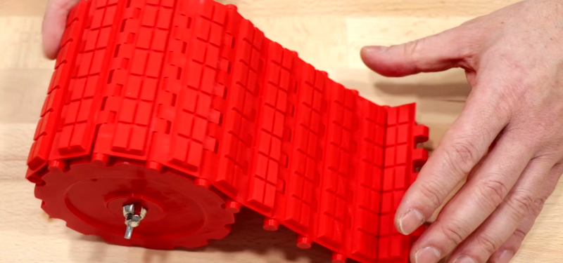
3D printed tank tracks are continuous tread systems made from printed links, belts, or flexible segments. They wrap around drive sprockets, idler wheels, and road wheels to move a vehicle across surfaces with more contact area than ordinary wheels. In practical maker terms, they are used most often for RC tanks, tracked robots, robotics education platforms, terrain rovers, cosplay props, scale models, and engineering prototypes.
A traditional continuous track spreads weight across a larger surface area, which can help a vehicle move over loose soil, carpet, gravel, grass, and other uneven terrain. A printed version follows the same basic principle, but with maker-friendly trade-offs. It may not survive the apocalypse, but it can absolutely survive a living room obstacle course, a school robotics lab, or a backyard test run if designed properly.
Why 3D Print Tank Tracks Instead of Buying Them?
Commercial tank treads are convenient, but they are not always the right size, shape, pitch, or style for a custom project. That is where 3D printing shines.
Customization
The biggest advantage is control. You can adjust the width, pitch, tread pattern, sprocket diameter, hinge style, and total track length. If your robot needs 78 links per side, you print 78. If it needs 79 because your frame grew by 6 millimeters after a “quick redesign,” you print one more and pretend this was the plan all along.
Fast Prototyping
3D printing lets you test multiple versions quickly. You can print one small section of track, test the hinge clearance, revise the sprocket tooth profile, and print again before committing to a full set. This is especially helpful because tank tracks are mechanical assemblies, and mechanical assemblies love exposing tiny mistakes.
Lower Cost for Small Projects
For hobby robotics and scale models, printed tracks can be affordable compared with specialty parts. The cost depends on filament, print time, failed prints, and whether your printer decides today is a “mysterious clicking noise” day. Still, printing your own links often makes sense for one-off projects.
Learning Value
Designing 3D printed tracks teaches mechanical design, tolerances, friction, drive geometry, material behavior, and patience. Especially patience.
Main Types of 3D Printed Tank Track Designs
1. Individual Link Tracks
This is the classic approach. Each track link is printed separately and connected with pins, rods, filament pieces, screws, or printed hinge features. Individual link tracks look realistic and are easy to repair because one damaged link can be replaced without reprinting the entire belt.
The downside is assembly time. A full RC tank or robot may need dozens of links per side. After the fiftieth link, you may begin questioning your life choices, but the finished result is usually worth it.
2. Print-in-Place Flexible Tracks
Print-in-place tracks are designed as connected sections that move right off the print bed. These can be clever and satisfying when they work, but they require excellent clearance settings and a well-tuned printer. If the gaps are too tight, the links fuse together. If they are too loose, the track wobbles like it has had too much coffee.
3. TPU Belt-Style Tracks
Some makers print tracks from flexible filament such as TPU. This can create a rubber-like belt with better grip than hard plastic. TPU is excellent for traction pads, flexible treads, and softer contact surfaces. However, printing long flexible tracks can be slow, stringy, and more demanding than printing PLA or PETG.
4. Hybrid Tracks
A hybrid design uses rigid printed links for structure and flexible TPU pads for grip. This is a smart option for RC tanks and indoor robots because PETG or PLA can handle the hinge geometry while TPU improves traction on smooth floors. Think of it as giving your robot sneakers.
Best Materials for 3D Printed Tank Tracks
The right material depends on the project size, terrain, load, speed, and how much abuse the tracks will take.
PLA: Easy but Brittle
PLA is the beginner-friendly choice. It prints cleanly, holds detail well, and is great for prototypes, display models, light-duty robots, and test links. However, PLA can be brittle, especially at thin hinge points. It may crack if the track is under high tension or if the robot is heavy.
Use PLA when you are testing geometry, building a small indoor project, or making a decorative scale model. Avoid relying on PLA for high-impact outdoor tracks unless you are comfortable replacing parts.
PETG: A Stronger Everyday Choice
PETG is often a better material for functional tank track links. It is tougher and less brittle than PLA, while still being easier to print than many engineering plastics. PETG works well for snap-fit parts, hinges, and mechanical assemblies when the printer is tuned correctly.
For many hobbyists, PETG is the sweet spot: strong enough for real movement, forgiving enough for desktop printers, and not so dramatic that it requires a heated chamber and a motivational speech.
TPU: Grip and Flexibility
TPU is a flexible material that can improve traction and impact resistance. It is useful for tread pads, flexible belts, and soft contact surfaces. TPU can bend repeatedly better than rigid materials, but it can also be harder to print. Slower speeds, dry filament, and a direct-drive extruder usually help.
Use TPU when grip matters more than stiffness. For example, a tracked robot driving on tile, polished concrete, or hardwood may benefit from TPU tread pads because hard plastic can slip like a dog wearing socks.
Nylon and Composite Filaments
Nylon can be excellent for durable mechanical parts, but it absorbs moisture and usually needs more careful printing. Carbon-fiber-filled filaments can add stiffness, but they may be abrasive and less suitable for hinge areas that need repeated bending. These materials are better for advanced builders who already understand their printer and are willing to tune settings carefully.
Important Design Features
Track Pitch
Pitch is the distance from one link connection point to the next. It must match the sprocket teeth. If the pitch is wrong, the track will skip, bind, climb the sprocket, or throw itself off with theatrical flair.
A common design method is to choose the track pitch first, then design the sprocket around it. For example, if each link advances 10 or 11 millimeters, the sprocket teeth should be spaced to engage that pitch smoothly. The sprocket is not just a fancy wheel; it is the handshake between the motor and the track.
Hinge Clearance
Clearance is one of the most important details in 3D printed tank tracks. Printed parts are never perfectly dimensioned, and moving joints need space. For FDM printing, a starting clearance of about 0.3 to 0.6 millimeters is often practical for moving links, depending on the printer, material, nozzle size, and layer height.
If you make the clearance too tight, the links may fuse or bind. Too loose, and the track may wobble, derail, or wear quickly. The best approach is to print a small test section before printing 150 links and discovering that every hinge is a tiny plastic brick.
Pin Style
Track links can be joined with printed pins, filament pieces, metal rods, screws, or wire. Metal pins are usually stronger and smoother, especially for heavier RC tanks or robots. Short pieces of 1.75 mm filament can work for lightweight models, but they may bend or wear over time.
Brass rod, steel wire, small bolts, or smooth shafts can improve durability. The trick is to design the hinge holes cleanly and leave enough wall thickness around them so the link does not split under load.
Tread Pattern
The outer tread pattern controls grip. Raised bars, chevrons, blocks, and rubber-like pads can all work. For indoor use, avoid overly aggressive hard plastic lugs that scratch surfaces. For outdoor use, deeper treads may help on dirt and grass, but they also increase print time and can catch debris.
Side Guides
Side guides help keep the track aligned on the wheels. Without guides, a track can walk sideways and fall off. Designs may use center guide teeth, side rails, flanged idlers, or sprocket geometry to keep everything tracking straight.
If your track keeps derailing, do not immediately blame the printer. Check wheel alignment, frame stiffness, sprocket engagement, tension, and whether the track has enough lateral guidance.
Sprockets, Idlers, and Tensioners
A track system is not just the track. The supporting hardware matters just as much.
Drive Sprocket
The drive sprocket transfers motor torque into the track. It must match the link pitch and engage the track securely without pinching it. A sprocket with too few teeth can feel jerky, while a larger sprocket can run more smoothly but requires more space.
Idler Wheel
The idler wheel sits at the opposite end of the track loop and helps guide the track. It may spin freely on bearings or bushings. Smooth idlers reduce friction and keep the system from wasting motor power.
Road Wheels
Road wheels support the vehicle weight along the bottom run of the track. Small models may use a simple skid plate instead, but rolling wheels usually reduce drag and improve performance.
Track Tensioner
Tension matters. A track that is too loose can derail. A track that is too tight can strain motors, crack links, wear pins, and make the whole vehicle sound like it is grinding pepper. A simple sliding idler, screw-adjusted tensioner, or spring-loaded arm can make a major difference.
For small robots, adjustable tension is one of the best upgrades you can add. It lets you fine-tune the system after printing, because real plastic parts rarely behave exactly like the CAD model promised.
Printing Settings That Usually Work
There is no universal slicer profile for 3D printed tank tracks, but these settings are a sensible starting point for FDM printers.
Layer Height
A 0.16 to 0.24 mm layer height usually balances detail and speed. Smaller layers can improve hinge surfaces and sprocket engagement, but they increase print time. For functional links, consistency is more important than showing off microscopic layer lines.
Wall Count
Use at least 3 walls for links that carry load. More walls increase strength around hinge holes and tread lugs. In many track links, wall count matters more than high infill because the stress lives near the surface and hinge geometry.
Infill
For small links, 40% to 100% infill may be reasonable, depending on size. Tiny links are often almost solid anyway. For larger tracks, 30% to 50% infill with strong walls may be enough.
Print Orientation
Orientation affects strength. Hinge loops are vulnerable if layer lines run in a direction that encourages splitting. Test different orientations and break a few sample links on purpose. It feels wrong, but destructive testing is cheaper than watching a full robot shed its tracks on the first run.
Supports
Good track designs avoid supports wherever possible. Supports inside hinge holes or between moving surfaces can create roughness and poor fit. If your design needs heavy supports, consider redesigning the link so it prints flat and clean.
Common Problems and How to Fix Them
The Track Is Too Tight
Add one link, reduce idler distance, or redesign the tensioner. Do not force a tight track and hope it “breaks in.” It may break, yes, but not in the helpful sense.
The Track Falls Off
Check alignment first. The sprocket, idler, and road wheels must be parallel. Add center guides, side flanges, or a better tension system. Also check whether the chassis flexes under load.
The Sprocket Skips
The pitch may not match, the teeth may be too shallow, or the track may be too loose. Print a small sprocket-and-link test before reprinting the entire drive system.
The Links Crack
Switch from PLA to PETG or nylon, increase wall count, thicken hinge barrels, reduce track tension, or use metal pins. Cracking usually means the design is concentrating stress in one tiny area.
The Tracks Slip on Smooth Floors
Add TPU pads, rubber strips, or a softer tread surface. Hard PLA on tile has roughly the same energy as tap dancing in dress shoes.
Best Uses for 3D Printed Tank Tracks
3D printed tank tracks are excellent for hobby and educational projects. They are especially useful for:
- RC tank models and custom scale vehicles
- Arduino or Raspberry Pi tracked robots
- STEM classroom projects
- Rover prototypes
- Camera slider platforms
- Cosplay props and display models
- Mechanical design demonstrations
They are not ideal for full-size vehicles, high-speed machines, heavy-duty outdoor equipment, or anything safety-critical. Printed plastic has limits, and respecting those limits is how you keep the project fun instead of expensive.
Step-by-Step Planning for Your First Track Project
Step 1: Define the Vehicle
Start with weight, size, motor power, terrain, and speed. A tiny desk robot and a 15-pound outdoor rover need very different tracks.
Step 2: Choose the Track Width
Wider tracks spread weight better and look more rugged, but they increase friction and print time. For small robots, wider is not always better.
Step 3: Pick the Link Pitch
Choose a pitch that fits your scale and sprocket size. Smaller pitch gives smoother motion but requires more links. Larger pitch is simpler but may run more roughly.
Step 4: Print a Test Link Set
Print five to ten links, assemble them, and bend them around a sample sprocket. This test can reveal hinge problems, pin fit issues, weak spots, and sprocket mismatch.
Step 5: Build One Complete Track
Do one side first. Install it, check tension, and drive slowly. Once the design works, print the second side using the same settings.
Step 6: Improve Traction
If the track slips, add TPU pads, texture, rubber strips, or softer tread inserts. If it digs too aggressively, reduce lug height.
Design Tips for Better Results
Keep the first version simple. Many beginners try to design a museum-grade suspension system before they have a track that can complete one lap around the sprocket. Start with a basic loop, prove the geometry, then add detail.
Use fillets around hinge barrels and tread bases. Sharp internal corners create stress points. A small radius can make the link stronger and easier to print.
Make replacement easy. Tracks are wear parts. Design your system so links can be removed without dismantling the entire robot. Future you will appreciate this, especially when current you drives the robot into a chair leg at full confidence.
Do not overtighten. A slightly loose track often runs better than a guitar-string-tight one. Real tracked systems usually have some sag, and printed systems benefit from not being under constant stress.
Finally, document your settings. Write down material, nozzle size, layer height, wall count, clearance, pin diameter, and link count. When you revisit the project later, you will not remember. Nobody remembers. That notebook is not decoration.
Real-World Experience: What Building 3D Printed Tank Tracks Teaches You
The first lesson from working with 3D printed tank tracks is that CAD is optimistic. On screen, every link rotates perfectly, every sprocket tooth engages politely, and the track glides like a luxury escalator. Then you print it, assemble it, and discover that one hinge is tight, one pin hole is oval, and the sprocket has the manners of a hungry raccoon. This is not failure. This is the project introducing itself.
In practice, the best workflow is slow and experimental. Print a short chain of links before printing a full set. A five-link test strip can tell you almost everything: whether the pins fit, whether the links flex enough around the sprocket, whether the tread lugs collide, and whether your material choice feels strong enough. This small test can save hours of print time and an impressive pile of regret spaghetti.
Another experience many makers share is that track tension is more important than expected. Beginners often think the track should be tight because tight looks controlled. But overly tight tracks increase friction, strain motors, and make small printed hinges suffer. A little slack can make the motion smoother. The goal is not to stretch the track into submission; the goal is to let it move predictably.
Material choice also becomes obvious once the vehicle actually drives. PLA is wonderful for shape testing, but on functional tracks it can feel hard and slippery. PETG usually behaves better for working links because it has more toughness. TPU is fantastic for grip, but using it for the entire track can make the system too stretchy unless the design accounts for that flexibility. A hybrid PETG-and-TPU design often feels like the practical middle ground: rigid structure where you need accuracy, soft contact where you need traction.
Surface testing can be humbling. A track that runs beautifully on carpet may slip on tile. A track that grips grass may collect dirt like it is starting a garden. A tread pattern that looks fierce may vibrate loudly on a hard floor. The best tread pattern depends on where the project will live. For an indoor RC tank, smooth TPU pads may beat aggressive plastic cleats. For a backyard rover, deeper lugs may help, but only if the motors have enough torque.
Assembly teaches patience. If your design uses metal pins, cut them consistently and deburr the ends. If you use filament as hinge pins, test whether it creeps or bends. If links are hard to assemble, slightly chamfer the holes or create a small lead-in. These tiny details make the difference between a project that is fun to maintain and one that requires tweezers, muttering, and possibly a snack break.
The most satisfying moment is the first successful loop around the sprocket. It may be slow. It may squeak. It may sound like a tiny plastic bulldozer crossing a kitchen table. But when the track engages, turns, and stays on, the whole project suddenly feels alive. That is the reward: not just a printed part, but a working mechanism you designed, tuned, and improved.
The best advice is to treat 3D printed tank tracks as a system, not a single part. Links, pins, sprockets, idlers, tensioners, wheels, motors, and terrain all interact. Improve one piece at a time. Test often. Expect revisions. And when your first track falls off after three feet, congratulate yourself. You have officially joined the ancient and noble order of people who thought, “Wheels are fine, but tracks are cooler.”
Conclusion
3D printed tank tracks are one of the most rewarding functional printing projects because they combine design, mechanics, material science, and a little bit of charming chaos. They let makers build custom RC tanks, tracked robots, and prototype vehicles with a level of flexibility that commercial treads cannot always provide.
The key is to design the entire drive system together. Match the sprocket to the track pitch. Leave enough clearance in the hinges. Choose the right material for the job. Add tension adjustment. Test small before printing big. If you follow those principles, your printed tracks can move smoothly, grip better, and survive more than one dramatic test drive across the living room.
Note: This article is intended for hobby robotics, educational projects, RC models, and general mechanical design. It is not intended for modifying real vehicles, weapons systems, or safety-critical machinery.