Holding a part to ±.002 inch sounds small because it is small. Very small. That is two thousandths of an inch on either side of the target dimension, or about 0.0508 mm. For perspective, a human hair may be several thousandths of an inch thick, which means this kind of tolerance lives in the same neighborhood as “please do not breathe too aggressively near the indicator.”
Yet in precision machining, marine repair, aerospace work, mold making, medical manufacturing, and high-quality fabrication, ±.002 inch tolerance is not magic. It is what happens when multiple elements converge: material behavior, machine condition, tooling, heat, fixturing, measurement, drawing clarity, and human judgment. When one element misbehaves, the part wanders. When all of them cooperate, the dial indicator stops dancing and the machinist gets to enjoy the rarest shop-floor emotion: peace.
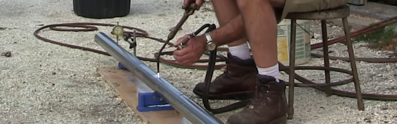
The phrase “The Elements Converge For ±.002 In Tolerance” fits especially well in the world of shaft straightening and precision repair. A long marine shaft, for example, may look like a simple cylinder, but over 17 feet of length it becomes a mechanical truth detector. Gravity, temperature, support location, residual stress, and tiny bends all show up. The shaft does not care how confident anyone felt during setup. It only reports what physics allows.
What ±.002 Inch Tolerance Really Means
A tolerance of ±.002 inch gives a total allowable variation of 0.004 inch. If a shaft diameter is specified at 2.000 inches ±.002, acceptable parts fall between 1.998 and 2.002 inches. If a straightness or runout requirement is held to a similar range, the challenge becomes more complex because the issue is no longer just size. It is geometry, alignment, and behavior under support.
That distinction matters. A part can be the correct diameter and still be wrong. A bore can measure within size and still be out of round. A shaft can look straight on a bench and then reveal runout when rotated. This is why precision manufacturing leans on geometric dimensioning and tolerancing, inspection planning, and repeatable measurement methods. The number on the print is only the beginning. The real question is: can the feature function as intended when assembled, loaded, heated, cooled, and used?
Why ±.002 Is Tight, But Not Impossible
In many CNC machining services, general tolerances commonly sit around ±.005 inch unless tighter requirements are called out. Moving to ±.002 inch often means the job has left the “standard machining” lane and entered the “everyone pay attention” lane. The shop may need better fixturing, sharper tools, slower finishing passes, more inspection time, and perhaps secondary operations such as grinding, honing, reaming, or boring.
The funny part is that ±.002 inch is both impressive and ordinary depending on context. On a small, rigid, well-supported part machined in one setup, it may be very achievable. On a long shaft, thin wall, plastic component, welded assembly, or heat-treated part, it can become a tiny dragon guarding the treasure chest.
The Main Elements Behind Precision Tolerance
1. Material: The Part Has a Personality
Material is never just “stuff.” Steel, aluminum, brass, copper, plastics, and nickel alloys all respond differently to cutting, clamping, heating, and cooling. Steel is relatively stable and strong, but it can carry internal stress from rolling, forging, welding, or previous machining. Aluminum conducts heat quickly and expands more than steel, which can make localized heat correction harder to control. Plastics may flex, creep, absorb moisture, or move after machining like they remembered an appointment elsewhere.
For ±.002 inch tolerance, material stability is not optional. A roughing pass may release stress. Heat treatment may distort geometry. Removing a part from a vise may allow it to spring. A long shaft may sag under its own weight. Precision work begins by admitting that the material is a participant, not a passive victim.
2. Machine Condition: Accuracy Starts Before the Cut
A CNC machine, lathe, mill, grinder, or straightening setup must be mechanically healthy. Worn ways, backlash, spindle runout, loose bearings, poor lubrication, unstable foundations, and thermal growth can all turn tight tolerances into shop comedy. Unfortunately, the customer rarely pays extra for comedy.
Thermal growth is especially sneaky. As a machine warms up, ball screws, spindles, castings, fixtures, and workpieces can expand. A dimension that looks perfect early in the morning may drift by lunch. This is why precision shops often warm up machines, monitor temperature, check offsets, and avoid measuring hot parts as though they were finished truth. At ±.002 inch, “close enough” needs a thermometer.
3. Tooling: The Cutter Must Behave
Cutting tools influence size, finish, roundness, straightness, and repeatability. A dull tool pushes instead of cuts. Excessive tool stickout invites deflection. Poor toolholders create runout. Vibration leaves chatter marks that look like the part tried to play a washboard solo.
For holes, the choice between drilling, reaming, and boring matters. A drill can make a hole quickly, but it may wander. A reamer improves diameter and finish. Boring offers more control over location, straightness, and cylindricity, though it may take longer. In precision work, the most efficient process is not always the fastest single operation. It is the process that makes good parts repeatedly without creating a scrap bin full of expensive little regrets.
4. Fixturing: Hold It Wrong, Measure It Wrong
Fixturing is where many tolerance dreams go to get humbled. A vise can bend a thin part. A chuck can distort tubing. Uneven support can mislead a runout reading. Clamping too hard may hold a part beautifully until it is released, at which point it springs into a shape nobody ordered.
For a long marine shaft, support points are critical. The shaft has weight, and weight creates sag. If the goal is to evaluate runout, the setup must allow the shaft to rotate repeatably while the indicator tracks variation. The measurement is less about whether the support board is a laboratory-grade artifact and more about whether the relationship between support, shaft, and indicator remains consistent. In other words, the setup must not become part of the mystery.
5. Heat: The Invisible Hand With a Torch
Heat straightening is a fascinating example of controlled distortion. The basic idea is to heat a localized area of metal, allowing expansion, plastic deformation, and then contraction during cooling. Used skillfully, the contraction can pull a bend in the desired direction. Used carelessly, it can turn a shaft into modern sculpture. Very avant-garde. Very unusable.
On a long shaft, heat straightening requires patience. The operator identifies high spots, applies heat in carefully chosen areas, cools or waits, checks movement, and repeats. The work becomes a conversation with the metal. The torch asks a question. The indicator answers. If the answer is rude, the next heat spot is adjusted.
This is where experience becomes hard to write into a procedure. The amount of heat, spot size, location, cooling method, shaft material, bend severity, and previous stress all matter. Two shafts with similar dimensions may not respond identically. That is why old-school straightening can look like wizardry, even though the wizard is really applying thermal expansion, contraction, and decades of “don’t do that again” knowledge.
Why Measurement Is the Judge, Jury, and Occasionally the Heckler
You cannot hold ±.002 inch tolerance if you cannot measure it. That sounds obvious, but it is one of the most common traps in precision work. A measuring tool must be accurate enough, repeatable enough, and appropriate for the feature. Calipers may be fine for general checks, but micrometers, dial indicators, bore gages, height gages, air gages, CMMs, optical comparators, or laser systems may be needed for tighter or more complex requirements.
A useful rule in many quality systems is that the measurement process should consume only a small fraction of the tolerance band. If the measuring system itself varies too much, it becomes impossible to tell whether the part is good or whether the inspection process is simply having a moody afternoon. For a ±.002 inch tolerance, repeatability and reproducibility are not paperwork decorations. They determine whether inspection results can be trusted.
Inspection Must Match the Feature
Checking a simple outside diameter is not the same as checking straightness, circular runout, total indicated runout, flatness, or true position. A micrometer may confirm diameter, but it will not prove a shaft runs true. A dial indicator can show variation during rotation, but the setup must be stable. A CMM can inspect complex geometry, but it needs a proper measurement plan, controlled environment, and clear datums.
This is where good drawings become powerful. A clear print tells the shop which features matter, which datums control the part, what tolerance applies, and what inspection method makes sense. A vague drawing says, “Please guess my intentions,” which is a bold strategy in manufacturing and usually a costly one.
Design Choices That Make ±.002 Easieror Painful
Designers influence tolerance success long before the part reaches a machine. A tolerance should reflect function, not anxiety. If every dimension is marked ±.002, the drawing may look serious, but the quote will look like it needs a small loan. Tight tolerances increase inspection time, setup complexity, scrap risk, and lead time. They should be reserved for features that truly affect fit, sealing, alignment, motion, balance, or safety.
For example, a bearing journal, seal surface, dowel hole, gear bore, or alignment feature may genuinely need tight control. A cosmetic edge, clearance pocket, or non-critical bracket length probably does not. Precision is valuable, but unnecessary precision is just expensive decoration.
GD&T Helps Communicate Function
Geometric dimensioning and tolerancing helps separate size from form, orientation, and location. Instead of relying only on plus/minus dimensions, GD&T can specify flatness, straightness, parallelism, perpendicularity, position, profile, circularity, cylindricity, and runout. This makes the design intent clearer and helps the manufacturer inspect what actually matters.
For a rotating shaft, runout may matter more than a simple straight-line dimension. For a mounting plate, flatness and hole position may matter more than overall length. For a precision bore, cylindricity and surface finish can be just as important as diameter. GD&T is not alphabet soup for engineers who own too many mechanical pencils. It is a language for making parts function.
Specific Example: Straightening a Long Marine Shaft
Imagine a 17-foot marine shaft that must run within ±.002 inch. The shaft is long enough to make handling difficult and precise enough to make casual methods risky. The operator supports it, rotates it, locates the high spots, marks the correction zones, and uses controlled heat to influence the metal. After each correction, the shaft is checked again.
The process is slow because metal does not accept motivational speeches. Heat too little and nothing meaningful happens. Heat too much and the correction overshoots. Cool unevenly and new distortion can appear. Move the supports carelessly and the reading changes. Let sunlight warm one side and the shaft may show a tiny but real shift. Suddenly the shop door, the weather, and the coffee break are all part of the process.
What makes the final ±.002 result impressive is not merely the number. It is the length of the part, the simplicity of the tools, and the skill required to use thermal behavior as a corrective force. CNC equipment is wonderful, but this kind of work reminds us that precision is not always hidden inside a control cabinet. Sometimes it stands beside a torch, squints at an indicator, and knows exactly where to apply heat next.
Common Mistakes When Chasing Tight Tolerance
Over-Tolerancing Everything
Putting ±.002 on every feature may feel safe, but it often causes unnecessary cost. It can force slower machining, extra inspection, secondary processes, and rejected parts that would function perfectly. Tight tolerances should be strategic.
Ignoring Temperature
Temperature changes can move dimensions. This is especially true for long parts, aluminum components, precision assemblies, and machine tools that warm during operation. Measuring a hot part and approving it as if it were at stable room temperature is an excellent way to meet the tolerance temporarily and disappoint everyone later.
Trusting the Wrong Tool
A caliper is useful, but it is not a universal truth machine. For ±.002 inch work, the inspection tool must be appropriate to the feature and the tolerance. The operator must also use it consistently. A world-class micrometer in careless hands is just an expensive clamp with numbers.
Forgetting Setup Rigidity
Flex, vibration, and poor support can ruin repeatability. If the fixture moves, the part moves. If the tool deflects, the cut changes. If the indicator stand shifts, the measurement becomes fiction with a needle.
Practical Experiences Related to ±.002 Inch Tolerance
Shop-floor experience teaches that ±.002 inch tolerance is less about one heroic move and more about a hundred small decisions made correctly. A machinist may begin by roughing a part slightly oversize, leaving enough stock for a stable finishing pass. That extra material is not laziness; it is insurance. Roughing removes stress, finishing refines geometry, and inspection confirms whether the plan survived contact with reality.
One common experience is watching a part measure perfectly while clamped, then change after release. Thin aluminum plates are famous for this trick. A vise squeezes them flat, the cutter makes a beautiful surface, and then the part relaxes into a curve as soon as clamping pressure disappears. The lesson is simple: if the final part will live unclamped, inspect it unclamped. The part does not care how straight it looked while held hostage.
Another familiar lesson comes from holemaking. A drilled hole may be acceptable for clearance, but when a dowel pin or bearing fit is involved, drilling alone may not be enough. The hole may need to be bored, reamed, or finished in a controlled sequence. The difference can be dramatic. A drill wants to follow convenience; a boring bar follows instruction. That is why experienced machinists choose the process based on the function of the hole, not just the diameter on the print.
Long shafts bring their own personality. Anyone who has indicated a long round bar knows the suspense of slowly rotating it and watching the needle rise and fall. The first reading may look discouraging. Then supports are adjusted, the surface is cleaned, burrs are removed, and the reading becomes more meaningful. If heat straightening is involved, the process becomes even more patient. The operator may heat a small area, wait, cool, rotate, check, and repeat. Progress can be measured in thousandths, which means celebration must be modest. No confetti near the lathe, please.
Temperature also creates memorable surprises. A part measured immediately after machining may be slightly expanded from cutting heat. A shaft sitting in sunlight may show movement that disappears in shade. A machine that has not warmed up may cut differently after an hour of operation. These experiences teach humility. At ±.002 inch, the environment is not background scenery; it is part of the manufacturing system.
The best shops develop habits that make tight tolerance less dramatic. They clean surfaces before measuring. They verify instruments. They use stable setups. They check first articles before running the whole batch. They separate roughing and finishing. They communicate when a tolerance is expensive, unclear, or functionally unnecessary. They know when to use CNC precision and when an experienced hand with a torch, indicator, and patience is the right tool for the job.
In the end, ±.002 inch tolerance feels most achievable when nobody treats it as a single number. It is a result created by design intent, material knowledge, machine health, process control, inspection discipline, and skilled judgment. When those elements converge, precision stops looking mysterious. It becomes the satisfying click of a dial indicator settling where it should.
Conclusion
The elements converge for ±.002 inch tolerance when precision is treated as a complete system. Material must be understood. Machines must be stable. Tooling must be rigid and sharp. Fixtures must hold without distorting. Heat must be respected. Measurements must be trustworthy. Drawings must communicate function instead of spreading tolerance panic across every dimension.
Whether the job is CNC machining a critical component, boring a precision hole, grinding a hardened surface, or heat-straightening a long marine shaft, the principle is the same: tight tolerance is earned. It is not achieved by wishing at the print or tapping the part three times with a lucky wrench. It comes from controlling the variables that matter and knowing which ones are quietly waiting to cause trouble.
Note: This article is written for web publication and synthesizes real-world precision machining, heat straightening, tolerance design, GD&T, CNC process control, tooling, thermal growth, and dimensional inspection practices without inserting source links or unnecessary reference tags.