If microcontrollers had a “quiet legend” category, the PIC 18F4550 dev board would be standing in the corner wearing safety glasses, holding a USB cable, and politely asking whether you remembered the crystal oscillator. This development board is built around Microchip’s PIC18F4550, an 8-bit microcontroller that became popular because it combines classic PIC reliability with native USB capability, generous I/O, analog inputs, timers, serial interfaces, and enough memory to build real embedded projects without immediately feeling trapped inside a broom closet.
For students, hobbyists, electronics instructors, and engineers who enjoy direct hardware control, the PIC 18F4550 dev board is still a practical learning platform. It is not the newest shiny chip on the shelf, and it will not pretend to be a Wi-Fi-enabled artificial intelligence robot toaster. What it does offer is something incredibly useful: a hands-on way to understand USB communication, embedded C programming, digital I/O, analog sensing, PWM control, serial communication, interrupts, bootloaders, and in-circuit programming.
This guide explains what a PIC 18F4550 development board is, what features matter, how it is commonly used, what beginners should watch out for, and why this board still deserves a spot on an electronics workbench.
What Is a PIC 18F4550 Dev Board?
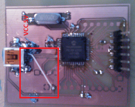
A PIC 18F4550 dev board is a ready-made circuit board designed to make the PIC18F4550 microcontroller easier to test, program, and connect to external components. Instead of wiring the chip, oscillator, USB connector, reset circuit, voltage regulator, ICSP header, LEDs, buttons, and power rails by hand every time, the development board places those essentials on one neat platform.
The PIC18F4550 itself is an 8-bit PIC18-family microcontroller from Microchip Technology. It is widely known for its built-in USB 2.0 full-speed support, 32 KB of Flash program memory, 2 KB of SRAM, 256 bytes of EEPROM, 13-channel 10-bit analog-to-digital conversion, multiple timers, PWM capability, and common communication interfaces such as UART, SPI, and I2C. In plain English: it gives you enough hardware tools to make buttons blink LEDs, sensors talk to computers, motors behave themselves, and USB projects feel less like dark magic.
Most PIC18F4550 dev boards expose the microcontroller pins through headers, add a USB connector for communication or programming, include a crystal oscillatoroften 20 MHzand provide an ICSP connector for use with programmers such as PICkit tools. Some boards also include LEDs, user push buttons, a reset button, a 5V voltage regulator, power jack, bootloader support, and prototyping areas.
Why the PIC18F4550 Became Popular
The PIC18F4550 earned its reputation because it sits in a useful middle ground. It is more capable than tiny beginner microcontrollers but still simple enough to understand at the register level. It supports USB without requiring an external USB controller, which was a major advantage for data acquisition, custom HID devices, USB-to-serial projects, lab instruments, and PC-connected control systems.
For many embedded learners, the PIC18F4550 is where microcontroller programming stops being only about blinking LEDs and starts becoming about communication. Once a project can talk to a computer through USB, the board becomes useful for dashboards, logging tools, control panels, virtual COM ports, measurement devices, and human interface devices. Suddenly, your little circuit is no longer lonely. It has a USB cable and a social life.
Core Features of a Good PIC 18F4550 Development Board
USB 2.0 Full-Speed Support
The headline feature is USB. The PIC18F4550 supports USB low-speed and full-speed operation, making it suitable for USB HID, CDC, custom USB device, data logging, and control applications. A good dev board should include a properly routed USB connector, the required support components, and a stable clock source configured for USB timing. USB is picky; it does not appreciate “close enough” clocking or casual wiring decisions made at 1:00 a.m.
20 MHz Crystal Oscillator
Many PIC18F4550 development boards use a 20 MHz crystal because it works well with the internal PLL settings needed to generate the USB clock. The device can operate up to 48 MHz under the right configuration, but beginners should remember that oscillator configuration bits matter. A perfect circuit with the wrong clock settings can behave like a locked door with a very expensive doorknob.
ICSP Programming Header
An ICSP header allows the PIC18F4550 to be programmed directly on the board using tools such as PICkit programmers/debuggers. This is important because it lets developers flash firmware, debug code, and recover from bootloader mistakes without pulling the chip out of its socket. For serious learning, ICSP support is not optional; it is your emergency exit.
Bootloader Support
Some PIC 18F4550 dev boards come with a USB bootloader or are designed to support one. A bootloader lets users upload firmware over USB without using an external programmer every time. This is convenient for classroom environments and rapid testing. However, a bootloader also occupies program memory and requires correct reset and entry behavior, so it should be treated as a useful tool rather than a magical unicorn.
Digital I/O Pins
The PIC18F4550 offers a healthy number of input/output pins, depending on package and board layout. Dev boards usually break these pins out to headers so users can connect LEDs, switches, sensors, LCDs, relays, motor drivers, keypads, or custom circuits. This makes the board flexible for both simple and moderately advanced projects.
Analog-to-Digital Converter
With 13 channels of 10-bit ADC, the PIC18F4550 can read analog sensors such as potentiometers, temperature sensors, light sensors, pressure sensors, and voltage dividers. For beginner projects, this makes it excellent for learning how the real world becomes digital data. For example, a potentiometer can control LED brightness, a temperature sensor can send values to a PC over USB, or a light sensor can trigger an alarm when someone opens a box of cookies that was clearly labeled “Do Not Touch.”
UART, SPI, and I2C Interfaces
The board can communicate with many external devices through UART, SPI, and I2C. UART is useful for serial modules and debugging. SPI can connect to displays, memory chips, ADCs, and fast peripherals. I2C is commonly used for sensors, real-time clocks, OLED displays, and compact modules. A well-designed dev board makes these pins easy to access without forcing you to perform surgery with jumper wires.
Common PIC 18F4550 Dev Board Applications
USB HID Devices
The PIC18F4550 is frequently used for USB Human Interface Device projects. HID devices can include custom keyboards, game controllers, button panels, control knobs, test tools, and simple PC interfaces. One advantage of HID is that many operating systems support it without requiring custom drivers, making it beginner-friendly compared with more complex USB classes.
USB CDC Virtual Serial Ports
A CDC project allows the board to appear as a virtual COM port on a computer. This is useful for sending sensor data, receiving commands, creating terminal-based control systems, or replacing traditional RS-232 communication with USB. For students, CDC projects are a gentle bridge between classic serial communication and modern USB connectivity.
Data Acquisition Systems
Because the PIC18F4550 includes ADC inputs and USB support, it works well for simple data acquisition. A dev board can read temperature, humidity, light, voltage, or other sensor data and send it to a computer for logging or display. This makes it useful in labs, classrooms, and small automation projects.
Motor and LED Control
With timers and PWM capability, the PIC18F4550 can control LED brightness, servo signals, DC motor speed through driver circuits, and other timing-based outputs. Of course, the microcontroller should not drive motors directly. That is how chips become tiny space heaters. Use proper driver circuits, flyback protection, and external power when needed.
Embedded Learning and Classroom Labs
The PIC 18F4550 dev board is excellent for teaching embedded systems because it exposes many core concepts in one platform: registers, configuration bits, interrupts, timers, ADC, USB, serial communication, and firmware flashing. Unlike ultra-abstract beginner boards, it encourages learners to understand what the hardware is actually doing.
How to Program a PIC 18F4550 Dev Board
The most common modern workflow uses MPLAB X IDE and the MPLAB XC8 compiler. MPLAB X provides the development environment, project management, device configuration, build tools, and debugging support. XC8 compiles C code for 8-bit PIC microcontrollers. A PICkit programmer/debugger can then load the compiled firmware into the chip through the ICSP header.
A typical workflow looks like this:
- Create a new MPLAB X project for the PIC18F4550.
- Select the XC8 compiler.
- Configure oscillator, watchdog timer, brown-out reset, USB voltage regulator, and other configuration bits.
- Write the firmware in C.
- Build the project and fix compiler errors.
- Connect the programmer to the ICSP header.
- Program the board and test the circuit.
- Debug, adjust, repeat, and try not to blame the breadboard too early.
For USB projects, Microchip software libraries and example projects can help, but users must match the firmware configuration to the board’s oscillator and hardware layout. A USB example written for one board may need clock and pin adjustments before it works on another.
PIC 18F4550 Dev Board vs Arduino Boards
Many beginners ask whether a PIC 18F4550 dev board is better than an Arduino. The honest answer is: it depends on the goal. Arduino boards are easier for quick prototyping, have enormous community support, and hide many low-level details. A PIC18F4550 dev board requires more attention to configuration bits, registers, datasheets, clock setup, and programming tools.
That extra effort is exactly why some people choose PIC. If your goal is to understand embedded systems deeply, the PIC18F4550 teaches valuable lessons. You learn why oscillator settings matter, how peripherals are configured, how USB timing works, and why datasheets are not decorative PDFs. Arduino often says, “Here is a library.” PIC often says, “Here is the register map; good luck, brave traveler.” Both approaches are useful, but they train different muscles.
What to Look for When Buying a PIC 18F4550 Dev Board
Clear Pin Labels
Good silkscreen labeling saves time and sanity. Look for boards that clearly mark ports, power pins, ground, analog channels, communication pins, reset, USB, and ICSP connections.
Stable Power Design
A board should include a reliable 5V supply option, proper decoupling capacitors, and clear instructions on whether it is powered by USB, external DC input, or both. Confusing power arrangements are a classic way to turn troubleshooting into archaeology.
Proper USB Connector and Clock Circuit
For USB work, the board should have a dependable connector, correct routing, a suitable crystal, and documentation for oscillator settings. USB projects are much easier when the hardware follows proven reference designs.
ICSP Compatibility
Make sure the board supports common Microchip programmers and exposes the correct ICSP pins. Even if the board includes a bootloader, ICSP access is valuable for recovery and debugging.
Documentation and Example Code
A dev board with a schematic, user manual, sample projects, and bootloader instructions is worth more than a mysterious green PCB from the land of “trust me, bro.” Good documentation can save hours of confusion.
Beginner Project Ideas for the PIC 18F4550 Dev Board
LED Blink With Timer Interrupt
Start with the classic LED blink, but use a hardware timer interrupt instead of a delay loop. This teaches timing, interrupts, and port control. It also proves your oscillator and programmer setup are working.
USB Button Panel
Create a USB HID device with several push buttons. Each button can send a command to a PC application. This is a practical introduction to USB HID reports and digital input handling.
Temperature Logger
Connect an analog temperature sensor to an ADC pin and send readings to a computer over USB CDC. This combines analog reading, formatting data, USB communication, and simple PC-side logging.
PWM LED Dimmer
Use PWM to control LED brightness based on a potentiometer reading. This project teaches ADC input, PWM output, scaling values, and real-time control.
I2C Sensor Display
Connect an I2C sensor and display the reading on an LCD or OLED module. This helps learners understand bus communication and external peripheral integration.
Common Problems and Practical Fixes
The Board Does Not Program
Check ICSP wiring, power supply, device selection in MPLAB X, programmer firmware, and whether MCLR is configured correctly. Also verify that the board is not being powered from two conflicting sources.
USB Is Not Recognized
USB issues often come from incorrect oscillator configuration, missing USB voltage regulator settings, wrong descriptors, poor cables, or firmware that never enables the USB module correctly. Try a known-good cable first. Many “USB bugs” are actually cables that only charge phones and refuse to carry data, because apparently even cables have career boundaries.
ADC Readings Are Noisy
Use proper grounding, decoupling, stable reference voltage, short sensor wires, and averaging in firmware. Separate noisy loads such as motors from analog inputs whenever possible.
Code Works Once, Then Fails Randomly
Look for watchdog timer settings, uninitialized variables, stack issues, power dips, floating input pins, and interrupt routines that take too long. Random behavior usually has a reason; it is just hiding under a pile of assumptions.
Best Practices for Working With the PIC 18F4550 Dev Board
Read the datasheet before blaming the chip. Keep a schematic nearby. Add comments to configuration bits because future-you will not remember why PLLDIV was set that way. Test one peripheral at a time. Use LEDs or serial output for simple debugging. Keep USB examples as close to known working configurations as possible before modifying them. Avoid connecting high-current loads directly to microcontroller pins. Label jumper wires if the project grows beyond three connections. And most importantly, change one thing at a time during troubleshooting.
The PIC18F4550 rewards patience. It is not always plug-and-play, but it is honest. When something fails, the cause is usually discoverable through clock settings, pin configuration, power, firmware, or wiring. That makes it a strong teaching tool and a satisfying platform for real embedded development.
Real-World Experience With the PIC 18F4550 Dev Board
Working with a PIC 18F4550 dev board feels different from working with beginner platforms that hide the difficult parts. At first, that can be annoying. You write a small program, hit build, connect the programmer, and then discover that the microcontroller is not running because one configuration bit is wrong. The board sits there silently, as if it knows the answer but wants you to grow as a person first.
The first useful experience is learning to respect clock configuration. USB projects especially force you to understand the relationship between the external crystal, PLL settings, CPU clock, and USB module clock. Many beginners assume that if the code compiles, the USB device should appear on the computer. The PIC18F4550 politely disagrees. The hardware clock must be correct, the USB module must be configured, descriptors must match the device class, and the firmware must service USB tasks properly. Once that clicks, USB stops being mysterious and becomes a structured system.
The second experience is appreciating ICSP programming. A USB bootloader is convenient, but a programmer such as a PICkit is the tool that saves the day when firmware breaks the bootloader entry condition or disables the wrong pins. In practice, keeping ICSP available makes experimentation much less stressful. It gives you permission to make mistakes, and mistakes are where embedded learning keeps most of its best snacks.
The third lesson is that board layout matters. A clean development board with labeled headers, stable power, decoupling capacitors, and a proper USB connector makes projects smoother. A poorly documented board can still work, but troubleshooting becomes slower. When using sensors, LCDs, or external modules, clear pin access and ground organization matter more than beginners expect. One loose ground wire can create symptoms that look like software bugs, hardware failure, and mild supernatural activity all at once.
The fourth experience is that the PIC18F4550 is excellent for learning disciplined embedded C. Because memory is limited compared with modern 32-bit boards, you naturally learn to keep code efficient. You pay attention to data types, buffers, interrupt routines, and peripheral setup. That discipline carries over to larger microcontrollers later. In other words, the PIC18F4550 may be 8-bit, but it teaches grown-up habits.
The fifth experience is how satisfying PC-connected projects can be. A simple ADC reading becomes more exciting when it appears in a terminal window. A button becomes more interesting when it controls software on a laptop. A homemade USB HID controller feels like a real device, not just a classroom exercise. The board gives beginners a clear path from blinking LEDs to building tools that communicate with computers.
Finally, the PIC 18F4550 dev board teaches patience without wasting time. It makes you check the datasheet, understand the schematic, verify the oscillator, confirm the power rails, and test the firmware step by step. That may sound old-school, but it is exactly the kind of experience that turns casual electronics curiosity into real embedded confidence. The board will not do everything for you, but it will teach you why everything works. That is a pretty good deal for a small PCB with a USB connector and a stubborn little microcontroller.
Conclusion
The PIC 18F4550 dev board remains a valuable platform for learning and building embedded USB projects. It combines the classic strengths of PIC microcontrollers with useful features such as USB 2.0 full-speed support, ADC inputs, serial interfaces, timers, PWM, EEPROM, and plenty of I/O. For beginners, it offers a serious introduction to microcontroller development. For experienced users, it remains useful for compact USB devices, data acquisition tools, control systems, and educational labs.
Its biggest advantage is not that it is the newest board available. Its biggest advantage is that it teaches the fundamentals clearly. You learn clocks, configuration bits, programming tools, USB communication, peripheral setup, and hardware troubleshooting. That knowledge does not expire when you move to newer microcontrollers. In fact, it makes every future board easier to understand.
If you want a development board that helps you go beyond copy-and-paste electronics and into real embedded design, the PIC 18F4550 dev board is still a smart, practical, and surprisingly fun choice. Just keep the datasheet close, double-check your oscillator settings, and never trust a USB cable until it has proven its loyalty.
Note: This article is written in original standard American English for web publishing and is based on real technical information about the PIC18F4550 microcontroller, development board features, USB development workflows, and common embedded programming practices.