Note: This article is written as original, publication-ready web content based on real Arduino, LED, microcontroller, and persistence-of-vision display principles.
A POV spinner display with Arduino is one of those projects that feels like a magic trick until you build it, debug it, drop one tiny screw on the floor, and suddenly understand physics at a deeply personal level. POV stands for persistence of vision, the visual effect that makes fast-moving lights appear as continuous shapes or floating text. Instead of using a full LED matrix, a POV display spins a small row of LEDs at high speed and flashes them at precise moments. Your eyes do the rest, politely filling in the blanks like a helpful intern with excellent timing.
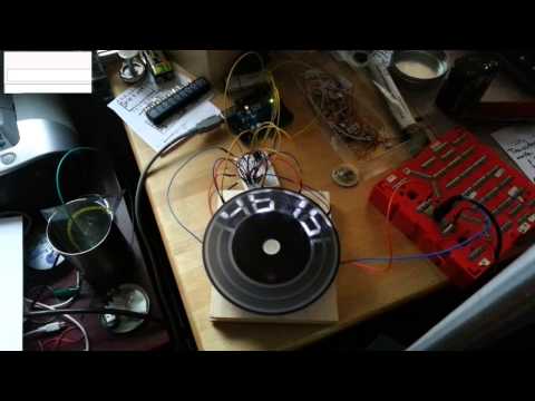
At its heart, this project combines an Arduino board, LEDs, resistors, a rotating arm or disk, a motor, a power source, and smart timing code. When the LEDs spin quickly enough, the Arduino turns individual LEDs on and off in columns. Those columns appear to hang in the air as words, icons, patterns, or simple animations. It is a beautiful example of embedded electronics, optical illusion, and maker-style problem solving packed into one spinning gadget.
The best part? A basic Arduino POV spinner display does not require a giant budget or industrial lab equipment. You can start with an Arduino Nano or Uno, a line of standard LEDs, a DC motor, and a few common electronic components. As the project grows, you can improve it with a Hall effect sensor, addressable LEDs, better power management, a balanced rotor, and custom bitmap graphics. In other words, it begins as a weekend project and quietly turns into a tiny engineering degree with blinking lights.
What Is a POV Spinner Display?
A POV spinner display is a rotating LED display that uses motion and timing to create the illusion of a complete image. Instead of lighting hundreds or thousands of LEDs at once, it uses a smaller number of LEDs and moves them through space. The Arduino controls when each LED flashes during rotation, so each flash becomes one slice of an image.
Imagine drawing a clock face. If you place LEDs along one hand of the clock and spin that hand rapidly, each LED passes through every angular position around the circle. If the Arduino knows where the arm is, it can flash the LEDs at exactly the right moments. After one full rotation, your eyes perceive a circular image, a word, or a pattern. The hardware is simple, but the timing needs to be sharp. This is where Arduino becomes the ringmaster of the tiny electronic circus.
How Persistence of Vision Works
Persistence of vision happens because the human visual system does not instantly erase an image the moment light disappears. When a bright LED flashes briefly and then moves away, the eye and brain retain that visual impression for a short time. If many flashes happen quickly in sequence, the brain blends them into one continuous image.
This same idea helps explain why movies look smooth, why LED displays can refresh rapidly without obvious flicker, and why waving a sparkler at night creates glowing trails. A POV display simply uses this effect intentionally. The Arduino does not create a complete image at one instant. It creates pieces of the image at very high speed, and your eyes assemble the pieces into something recognizable.
Main Components Needed for an Arduino POV Spinner
A typical Arduino POV spinner display uses a mix of mechanical and electronic parts. The exact list depends on whether you want a simple text display, a circular clock-style display, or a higher-resolution full-color spinner.
Arduino Board
An Arduino Nano is a popular choice because it is small, lightweight, affordable, and easy to mount on a rotating arm. An Arduino Uno is excellent for prototyping on a desk, although it can be bulky for the final spinning assembly. For faster or more colorful displays, makers sometimes use more powerful boards, but a Nano is enough for many beginner and intermediate POV projects.
LEDs
For a basic build, you can use 8 to 16 standard 5 mm LEDs in a straight line. Each LED represents one vertical pixel position. Add resistors to limit current and protect the LEDs. Common resistor values such as 220 ohms or 330 ohms are often used, depending on LED color, supply voltage, and brightness goals.
For advanced projects, addressable LED strips such as APA102 or DotStar-style LEDs are often better than slower single-wire RGB LEDs. Faster refresh performance matters because the LEDs are moving quickly. If the LED update speed is too slow, the image can look dotted, stretched, or messy. In POV displays, timing is not a polite suggestion; it is the entire show.
Motor
A small DC motor can spin the display arm. The motor should be strong enough to rotate the assembly smoothly but not so wild that the project turns into a flying LED boomerang. A recycled fan motor, hobby DC motor, or carefully mounted brushless motor can work. The most important factors are stable speed, safe mounting, and good balance.
Rotation Sensor
A Hall effect sensor with a small magnet is one of the most useful upgrades for a POV spinner display. Each time the magnet passes the sensor, the Arduino gets a reference point. This tells the code where the rotation begins. Without a rotation reference, the display may drift, wobble, or smear because the Arduino is guessing where the image should start.
Power Source
Power can be supplied by a battery mounted on the spinning arm, slip rings, or a stationary supply depending on the design. For simple builds, a small battery pack is convenient, but weight balance becomes very important. If the battery is heavy and placed off-center, the spinner may vibrate like a washing machine full of sneakers.
Basic Working Principle
The Arduino stores a pattern in memory. This pattern may be text, numbers, symbols, or a simple bitmap. The image is divided into columns. During rotation, the Arduino outputs one column at a time to the LED row. After a tiny delay, it outputs the next column. When the rotating arm completes a full circle, the sequence starts again.
For example, if the display uses 8 LEDs vertically and 60 angular columns around the circle, the Arduino must update the LED pattern 60 times per rotation. If the spinner rotates 20 times per second, the Arduino must handle 1,200 column updates per second. That is manageable, but the code needs to be lean. Long delays, unnecessary calculations, or slow serial printing can ruin the effect.
Simple Circuit Design
A basic POV spinner circuit can be built with an Arduino Nano, 8 LEDs, 8 current-limiting resistors, a motor, and a power supply. Each LED connects to a digital output pin through a resistor. The other side of the LEDs connects to ground. The Arduino turns each pin HIGH or LOW to control the LEDs.
For better brightness control, PWM-capable pins can be used, but many simple POV displays work fine with direct digital output. The key is fast switching. Each LED must flash for a very short period while the arm is in the correct position. If the LED remains on too long, the image stretches. If it is too dim or too brief, the image becomes faint.
Example LED Pattern Logic
The code often stores letters as arrays of binary values. Each number represents which LEDs should turn on for one column. For instance, an 8-bit value can control 8 LEDs. A binary value of 11111111 turns all LEDs on, while 00011000 turns on only the middle LEDs. By arranging these columns in sequence, the Arduino can draw letters.
This is a simplified example, but it shows the idea. The Arduino does not think in terms of “draw the letter A.” It thinks, “turn these pins on, now these pins, now these pins.” Very literal. Very obedient. Slightly robotic, which is fair.
Why Timing Matters So Much
Timing is the difference between a crisp floating message and a glowing blur that looks like a UFO sneezed. The Arduino must know how fast the arm is spinning and how long each column should remain visible. If the motor speed changes, the timing must change too.
That is why a Hall effect sensor is so valuable. The Arduino can measure the time between rotations, calculate the current rotation period, and divide that period by the number of image columns. This produces a dynamic column delay that adapts to motor speed changes.
Timing Example
Suppose one full rotation takes 50 milliseconds. If your image has 100 columns, each column gets 0.5 milliseconds. If the motor speeds up and a rotation takes 40 milliseconds, each column gets 0.4 milliseconds. The Arduino must keep up, or the image will shift.
This is also why simple delay-based sketches can work for demonstrations but become unreliable in polished builds. For smoother results, use interrupts for rotation detection and avoid code that blocks the main loop for too long.
Choosing Between Standard LEDs and Addressable LEDs
Standard LEDs are great for learning. They are cheap, bright, easy to understand, and excellent for single-color text. The downside is wiring. Each LED needs a control pin or driver arrangement, and the wiring can become messy as the display grows.
Addressable LEDs are more flexible. With RGB addressable LEDs, each LED can show different colors, making animations and graphics more exciting. However, not all addressable LEDs are equally suited for POV. In fast-moving displays, update speed and refresh behavior matter. Faster two-wire LEDs, such as APA102-style LEDs, are often preferred for high-speed persistence-of-vision projects because they allow rapid data and clock communication.
If your goal is a beginner-friendly Arduino POV spinner display, start with regular LEDs. If your goal is full-color graphics, consider faster addressable LEDs and a microcontroller with enough memory and processing power.
Mechanical Design: The Part Everyone Underestimates
Many beginners focus on the Arduino code first, but the mechanical build can make or break the project. A POV spinner display is a rotating object, which means balance, fastening, and safety matter. A perfectly written sketch cannot save an arm that wobbles like a noodle on a trampoline.
The LED strip or LED row should be mounted securely to a lightweight arm. The Arduino, battery, and wiring should be arranged so the spinning assembly is balanced around the motor shaft. If one side is heavier, vibration increases, the motor struggles, and the display becomes unstable.
Safety Tips
Always test at low speed first. Keep loose wires away from the motor shaft. Use protective glasses when experimenting with a new rotor. Do not spin heavy or sharp parts. Make sure batteries are firmly attached. A spinning battery pack is not a feature; it is a tiny emergency with voltage.
Programming the Arduino POV Display
The Arduino sketch for a POV spinner display usually has three main jobs: store the image data, detect rotation position, and output LED columns at the right time. The simplest version loops through column data with fixed delays. More advanced versions use a sensor interrupt to synchronize every rotation.
A practical program structure might include:
- An array that stores letter or bitmap data
- A setup section that configures LED pins as outputs
- An interrupt routine that records each rotation reference point
- A main loop that displays columns based on calculated timing
- Optional brightness control using PWM or current settings
Keep the display routine efficient. Avoid heavy math inside the fastest part of the loop. Precompute patterns where possible. Turn off LEDs between columns if ghosting appears. Use direct port manipulation only if standard digital output becomes too slow for your design, and only after you understand the tradeoffs.
Common Problems and Fixes
The Image Looks Blurry
Blurry images usually come from poor timing, motor speed changes, LEDs staying on too long, or mechanical wobble. Add a Hall effect sensor, shorten the LED on-time, improve balance, and make sure the motor speed is stable.
The Text Appears Backward
This happens when the column order or rotation direction is reversed. Flip the data order in code or rotate the spinner in the opposite direction. Congratulations, you have invented mirror writing, but probably not on purpose.
The Display Flickers
Flicker can come from low rotation speed, weak power, slow LED refresh, or inefficient code. Increase the motor speed gradually, improve the power supply, reduce unnecessary delays, and use LEDs that can update fast enough for motion.
The Spinner Vibrates
Vibration is usually mechanical. Balance the arm, secure the wiring, center the motor shaft, and reduce weight. A stable spinner creates a cleaner image and is much safer to operate.
Creative Ideas for a POV Spinner Display With Arduino
Once the basic display works, the project opens up many creative possibilities. You can show your name, display a clock, create a spinning logo, build a mini hologram-style decoration, or make a holiday ornament that writes messages in the air. Add a real-time clock module, and your spinner can show the time. Add Bluetooth or serial input, and you can update the message without reprogramming the Arduino every time.
You can also experiment with fonts. Simple block letters are easiest, but custom fonts make the display more personal. Small icons, arrows, hearts, stars, and simple pixel art work well. Large detailed images require more columns, faster updates, and better synchronization, so start simple and grow the project step by step.
Experience Notes: What Building a POV Spinner Teaches You
Building a POV spinner display with Arduino teaches lessons that are hard to absorb from theory alone. The first lesson is that electronics and mechanics are best friends, but they argue constantly. On the breadboard, your LEDs may blink perfectly. The moment you mount them on a spinning arm, wire length, vibration, balance, battery weight, and loose connections all become part of the circuit. The project reminds you that real-world electronics do not live in diagrams. They live on desks covered in jumper wires, coffee mugs, and one missing resistor that was definitely there a minute ago.
Another valuable experience is learning how visual timing feels. At first, you may think turning LEDs on and off is simple. Then you realize that a few milliseconds can decide whether your word appears sharp, stretched, reversed, or completely alien. You begin to appreciate why refresh rates, interrupts, and rotation sensing matter. Watching a messy blur slowly become readable text is incredibly satisfying. It feels less like debugging and more like tuning a musical instrument, except the instrument is made of LEDs and occasionally threatens to unscrew itself.
Power management also becomes very real. A POV spinner needs enough current for bright LEDs, but the power system must stay lightweight and safe. A battery that works nicely on the table may become a balance problem on the rotor. A long wire may tug. A weak connection may cut power for a split second during rotation. These small problems teach practical design thinking. You stop asking only, “Does the circuit work?” and start asking, “Will it still work while spinning at high speed for ten minutes?” That is a much better engineering question.
One of the best experiences is improving the project through tiny changes. Moving a battery closer to the center can reduce vibration. Adding a sensor can stabilize the image. Adjusting column delays can sharpen text. Changing LED brightness can make the display easier to read in a bright room. Each improvement is visible, which makes the project rewarding for beginners and experienced makers alike.
A POV spinner display also teaches patience. The first version may not look like the polished videos online. It may show half a letter, a sideways line, or something that resembles a haunted barcode. That is normal. Every failed test gives you information. Once you understand whether the problem is timing, wiring, motor speed, or balance, the project becomes easier to control. By the end, you do not just have a spinning display. You have a stronger understanding of Arduino programming, LED control, sensor feedback, and mechanical design.
Most importantly, the project is fun. It turns invisible timing into visible art. It makes code feel physical. It lets a handful of LEDs draw in midair. For anyone learning Arduino, a POV spinner display is a memorable project because it combines creativity with real technical depth. It is simple enough to start, challenging enough to respect, and flashy enough to impress anyone who walks into the room and asks, “Wait, how is that doing that?”
Conclusion
A POV spinner display with Arduino is a brilliant project for makers who want to combine programming, electronics, optical illusion, and hands-on mechanical design. The core idea is simple: spin a row of LEDs and flash them at precise times. The learning behind that simple idea is rich. You work with digital outputs, LED current limiting, timing loops, interrupts, sensors, motor stability, and image mapping.
For beginners, the best path is to start small with standard LEDs and a fixed message. Once that works, add rotation sensing, improve the rotor balance, and experiment with better graphics. Advanced builders can move toward addressable LEDs, full-color animation, wireless message updates, and high-speed synchronization. Whether you build a simple glowing name tag or a polished circular display, the Arduino POV spinner is a project that rewards curiosity, careful testing, and a healthy respect for spinning objects.
In short, this project proves that you do not always need a huge screen to make a display. Sometimes all you need is a microcontroller, a few LEDs, clever timing, and the willingness to let physics do the graphic design.