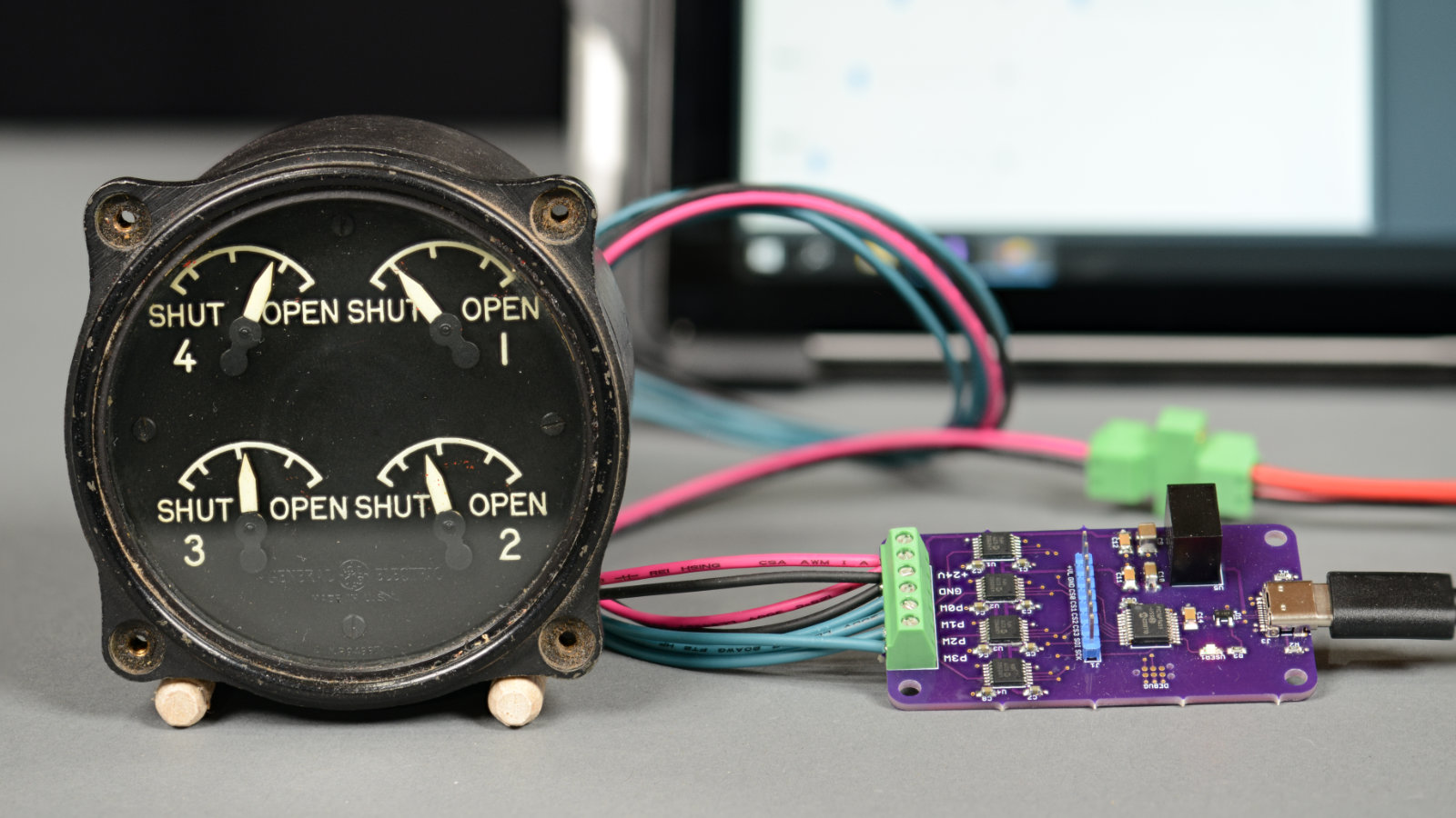
Some electronics projects begin with a development board, a datasheet, and a sensible plan. Others begin with a World War II-era aircraft engine cowl flaps indicator sitting on the bench, silently daring someone to make it talk to a modern computer. Interfacing an old engine cowl flaps indicator to USB is exactly that kind of project: part aviation history, part embedded electronics, part “why is this thing built like it expects to survive a thunderstorm inside a bomber?”
At first glance, an engine cowl flaps indicator looks like a simple cockpit gauge. In reality, it is a compact electromechanical position display designed for serious work. In piston-engine aircraft, especially air-cooled warbirds and larger radial-engine aircraft, cowl flaps help regulate cooling airflow around the engine. Open them during high-power, low-speed operations such as takeoff or climb, and the engine gets more cooling air. Close them in cruise, and the aircraft reduces drag while keeping temperatures under control. The indicator gives the crew visual feedback on where those flaps actually are.
Bringing such an indicator into the USB age is not about making an antique blink for fun. It is about understanding how the original instrument worked, replacing the missing aircraft sender hardware with modern electronics, and creating a clean bridge between a computer and a vintage analog display. The result can become a beautiful flight simulator accessory, a museum exhibit, a desk conversation piece, or the world’s most overqualified progress bar.
What Is an Engine Cowl Flaps Indicator?
An engine cowl flaps indicator is a cockpit instrument that shows the position of adjustable cooling doors in an aircraft engine cowling. These doors, or flaps, allow more or less air to flow through the engine compartment. In older air-cooled piston aircraft, temperature management was not a casual detail. Too little cooling could push cylinder head and oil temperatures too high. Too much cooling could create unnecessary drag or shock-cool components if handled carelessly.
Many vintage indicators were not digital devices in the modern sense. They were analog, magnetic, rugged, and built around the electrical systems of their time. A notable example is the General Electric 8DJ4PBV DC Selsyn indicator, a multi-needle gauge intended for four-engine aircraft. Each needle corresponds to one engine’s cowl flap position, giving the pilot or flight engineer a quick view of all four systems.
The charm of the instrument is that it does not need a screen, firmware update, cloud account, or subscription. It simply moves needles. That simplicity, however, hides a clever electromechanical design.
How the Old DC Selsyn Indicator Works
The DC Selsyn system used in many aircraft position indicators is based on magnetic field orientation. In the original aircraft installation, a transmitter attached to the moving flap mechanism acted much like a potentiometer. As the cowl flap moved, the transmitter changed the voltage sent to the indicator.
Inside the indicator, coils arranged around a magnetic rotor respond to that changing voltage. As current through the coils changes, the magnetic field shifts. The rotor, attached to the visible pointer, follows the magnetic field and moves the needle across the scale. It is analog feedback in the most literal sense: motion becomes voltage, voltage becomes magnetism, and magnetism becomes a needle position.
Many of these indicators were designed around 24-volt aircraft electrical systems. That detail matters. A USB port provides 5 volts, and often much less current than a vintage aircraft instrument expects. Therefore, the USB connection should be treated as the data link, not the main power source for the indicator. A separate regulated 24-volt supply is typically required for the instrument side, while the microcontroller and logic circuitry run at 5 volts or 3.3 volts depending on the design.
The Core Challenge: Replacing the Aircraft Sender
The old indicator expects to see the electrical behavior of its original sender. In a real aircraft, the sender would be mechanically linked to the flap actuator. On a workbench, that actuator is gone. The task is to create an electronic substitute that can generate the equivalent position signal for each needle.
There are several ways to approach this. A simple experimental setup might use manual potentiometers to test needle movement. Turn the knob, watch the needle move, take notes, and try not to grin too much. For a USB-controlled project, though, manual knobs are not enough. The computer needs a way to command each needle position.
That is where high-voltage digital potentiometers become useful. A part such as Microchip’s MCP41HV31 can act like a digitally controlled resistance element while tolerating higher analog voltages than ordinary low-voltage digital pots. In a practical four-engine indicator project, four digital potentiometers can control four independent needles. A microcontroller receives commands over USB, sends control data over SPI to the digital pots, and the indicator responds as though it were still listening to aircraft transmitters.
Choosing the USB Microcontroller
A good USB interface starts with a microcontroller that can speak USB without needing a pile of extra parts. The Microchip PIC16F1459 is a strong fit for this type of project because it includes full-speed USB capability and enough resources for a focused embedded task. The job is not to run artificial intelligence, render graphics, or calculate orbital mechanics. It simply needs to enumerate as a USB device, receive output reports from the computer, and update the digital potentiometers.
Other boards can also work. Arduino Leonardo, Arduino Micro, Teensy boards, RP2040-based boards, and many STM32 development boards can present themselves as USB devices. The right choice depends on the builder’s comfort level, preferred development tools, and whether the project needs to behave as a custom HID device, a virtual serial port, a joystick, or a simulator-specific interface.
For a vintage indicator display, a custom USB HID device is often elegant. HID devices can exchange small reports with the host computer and usually do not require a custom kernel driver on common operating systems. The report might be as simple as four bytes, one byte per needle, where each value represents a commanded cowl flap position.
Mapping Needle Position to Digital Values
Once the hardware can move the needles, the next challenge is calibration. Vintage instruments are wonderfully physical, which means they may not behave like perfect math. One needle may reach “open” slightly earlier than another. The scale may not be perfectly linear. Springs, magnets, internal resistance, age, and mechanical wear can all add personality. Old avionics do not have bugs; they have character.
A practical calibration process starts with minimum and maximum values. Send the lowest safe digital potentiometer setting and record the needle position. Then send the highest expected setting and record the other endpoint. Next, test several intermediate values and build a mapping table. If the movement is reasonably linear, a simple formula may be enough. If not, a lookup table can make the display feel more accurate.
For example, a host application might translate simulator cowl flap position from 0 to 100 percent into a 0 to 127 digital potentiometer command. If engine one reads slightly low at mid-scale, the software can compensate. The goal is not laboratory perfection. The goal is believable, repeatable movement that matches the visual language of the original instrument.
Connecting the Indicator to a Flight Simulator
The most satisfying use for a USB cowl flaps indicator is a home cockpit or desktop flight simulator. In Microsoft Flight Simulator, Prepar3D, X-Plane, and FlightGear, aircraft systems are represented by simulation variables, datarefs, properties, commands, or events. The software side of the project reads the simulated cowl flap position and sends a scaled value to the USB device.
In X-Plane, datarefs can expose per-engine cowl flap positions. In Microsoft Flight Simulator, SimConnect provides access to many engine-related simulation variables, although builders should verify the best current variable for the aircraft they are targeting because aircraft add-ons may use custom logic. In FlightGear, aircraft properties can often be accessed or bound through its property system. The concept is the same across platforms: read the simulator’s engine cooling flap position, scale it, and transmit it to the hardware.
A small desktop application written in C#, Python, or another familiar language can act as the bridge. It reads simulator data, opens the USB HID device, and sends position reports at a reasonable update rate. The indicator does not need hundreds of updates per second. Smooth, stable motion is more important than frantic USB chatter.
Power, Grounding, and Protection
Because the indicator side may use 24 volts, power design deserves respect. Use a regulated DC supply with appropriate current capacity, include fusing or current limiting, and separate the high-voltage instrument path from the USB logic path as cleanly as practical. The microcontroller may run from a 5-volt regulator derived from the 24-volt input, or from USB power if the design isolates responsibilities carefully.
Grounding should be planned rather than improvised. The digital potentiometers, microcontroller, and indicator reference points must agree electrically where the circuit requires it, but noisy wiring should be minimized. Decoupling capacitors near digital ICs, short SPI traces, good connector strain relief, and clear labeling all make the project more reliable.
The connector is another important detail. Many aircraft instruments use circular military-style connectors. These are sturdy, attractive, and very good at making beginners question their soldering choices. Use heat-resistant wire insulation where possible, add heat shrink to protect solder cup joints, and document every pin. Future you will be grateful. Future you is also the person most likely to forget which olive-drab connector pin was “engine three open-ish.”
Building the USB Control Workflow
A clean workflow can be divided into five stages. First, identify the instrument model and pinout. Second, test one indicator channel with a bench supply and a controlled resistance or digital potentiometer circuit. Third, build a single-channel prototype and confirm that the needle moves through the expected range. Fourth, expand to four channels. Fifth, create the USB protocol and host software.
This staged approach prevents expensive frustration. If the USB firmware is not working, you can still test the analog side. If one digital potentiometer channel behaves badly, you do not have to debug the entire simulator connection at the same time. Old instruments reward patience, and they punish “let’s solder everything and hope.”
For the USB protocol, keep it simple. A report that updates all four needles at once is easy to understand. For example, byte one controls engine one, byte two controls engine two, and so on. A second report type can update a single needle for testing. Add a status LED to the board so you can tell whether the device is powered, enumerated, or receiving data. Blinking lights do not solve every problem, but they make debugging feel less like staring into a small expensive cave.
Common Problems and Practical Fixes
Needles Do Not Move
Check the 24-volt supply, instrument pinout, digital potentiometer wiring, and whether the microcontroller is actually sending SPI commands. Confirm with a single channel before blaming the entire design.
Needles Move Backward
The scaling may be inverted, or the equivalent sender connections may be reversed. This is usually a software mapping problem unless the wiring is truly backwards.
Movement Is Jerky
Digital potentiometer resolution, update rate, and calibration can all affect smoothness. Try slower updates, interpolation in the host software, or a higher-resolution control method if the display needs finer movement.
USB Connects but the App Cannot Control It
Verify the HID report descriptor, vendor ID, product ID, report length, and permissions. A device can enumerate correctly and still ignore reports if the host and firmware disagree about report structure.
Why This Project Is Worth Doing
Interfacing an old engine cowl flaps indicator to USB is more than a neat electronics trick. It preserves the feel of real aviation hardware. Modern glass cockpits are powerful, but a physical needle has a special honesty. It moves because current, magnetism, and mechanics agree. When connected to a simulator, that movement adds depth that a flat screen cannot fully imitate.
The project also teaches several valuable engineering lessons. You learn how legacy aircraft instruments represented position. You learn how digital potentiometers can emulate analog behavior. You learn USB HID basics, embedded firmware design, calibration, simulator data integration, and practical hardware debugging. It is a compact course in applied electronics disguised as a vintage cockpit restoration.
Extra Experience Notes: Lessons From Working With Vintage Indicators
The first experience most builders have with a vintage cowl flaps indicator is surprise. These instruments feel heavy for their size, the pointers move with a deliberate mechanical grace, and the connector usually looks like it was designed by someone who believed “desktop use” meant “bolted to a vibrating aluminum airframe at altitude.” That ruggedness is part of the appeal, but it also means you should treat the instrument like an unknown historical artifact rather than a random panel meter.
Before applying power, spend time with inspection. Look for bent pins, loose glass, cracked insulation, corrosion, missing screws, and signs that someone already “repaired” it with heroic confidence and questionable solder. Measure coil resistance if the pinout is known. If the instrument has four channels, compare them. Similar readings across channels are reassuring; one channel that is wildly different deserves more investigation.
Another useful experience is to avoid rushing straight into USB. USB is not the magic part. The magic part is proving that the indicator can be controlled safely and repeatably. A bench test with current limiting and one channel connected can teach more in ten minutes than three hours of firmware guessing. Once a needle responds predictably to a controlled analog signal, the rest of the project becomes much less mysterious.
Mechanical behavior also matters. A vintage pointer may stick slightly at one end of the scale or settle differently depending on whether it approaches a value from above or below. This does not automatically mean the instrument is bad. It may simply reflect age, friction, spring tension, or the original design tolerance. In software, gentle smoothing and calibration tables can make the display look natural without pretending the instrument is a laboratory-grade servo.
For simulator builders, the most important lesson is to match the hardware to the aircraft. Not every simulated aircraft models cowl flaps in the same way. Some expose a standard variable. Some use custom local variables. Some do not simulate cowl flaps deeply at all. Before building a polished enclosure, confirm that your favorite aircraft can provide the data you want. Otherwise, your beautiful indicator may become a four-needle decoration that only moves when you run a test app. Still cool, but less useful.
Enclosure design is another place where experience helps. A vintage aircraft indicator looks best when mounted with respect. Give it a clean panel, secure the connector, provide ventilation for the power electronics, and make the USB and power inputs easy to disconnect. Label the back panel. Add a small fuse. Leave enough room so the connector cable is not bent sharply. A project that looks tidy is easier to maintain, and it also makes the whole build feel intentional rather than improvised.
Finally, keep the purpose clear. This type of USB conversion is for simulation, education, display, and restoration-style experimentation. It is not a shortcut for installing modified uncertified hardware in a real aircraft. That boundary does not make the project less exciting. It makes it responsible. On a desk or in a home cockpit, an old cowl flaps indicator can enjoy a second life, moving again after decades of silence, this time commanded by packets instead of a wartime aircraft sender.
Conclusion
Interfacing an old engine cowl flaps indicator to USB combines vintage aviation hardware with modern embedded design. The key is to respect the original instrument’s electrical behavior while replacing the missing aircraft transmitter with controlled electronics. A USB microcontroller, high-voltage digital potentiometers, a regulated 24-volt supply, careful calibration, and simulator-aware software can turn a forgotten cockpit gauge into a working USB peripheral.
It is the kind of project that rewards curiosity. You begin with an old indicator and end with a deeper understanding of aircraft systems, magnetic movement, HID communication, and practical hardware design. Also, you get moving needles. Never underestimate the motivational power of moving needles.
Note: This article is intended for educational, simulator, restoration, and hobby electronics use only. Modified vintage aircraft instruments should not be installed in real aircraft unless evaluated and approved through the proper aviation maintenance and certification processes.