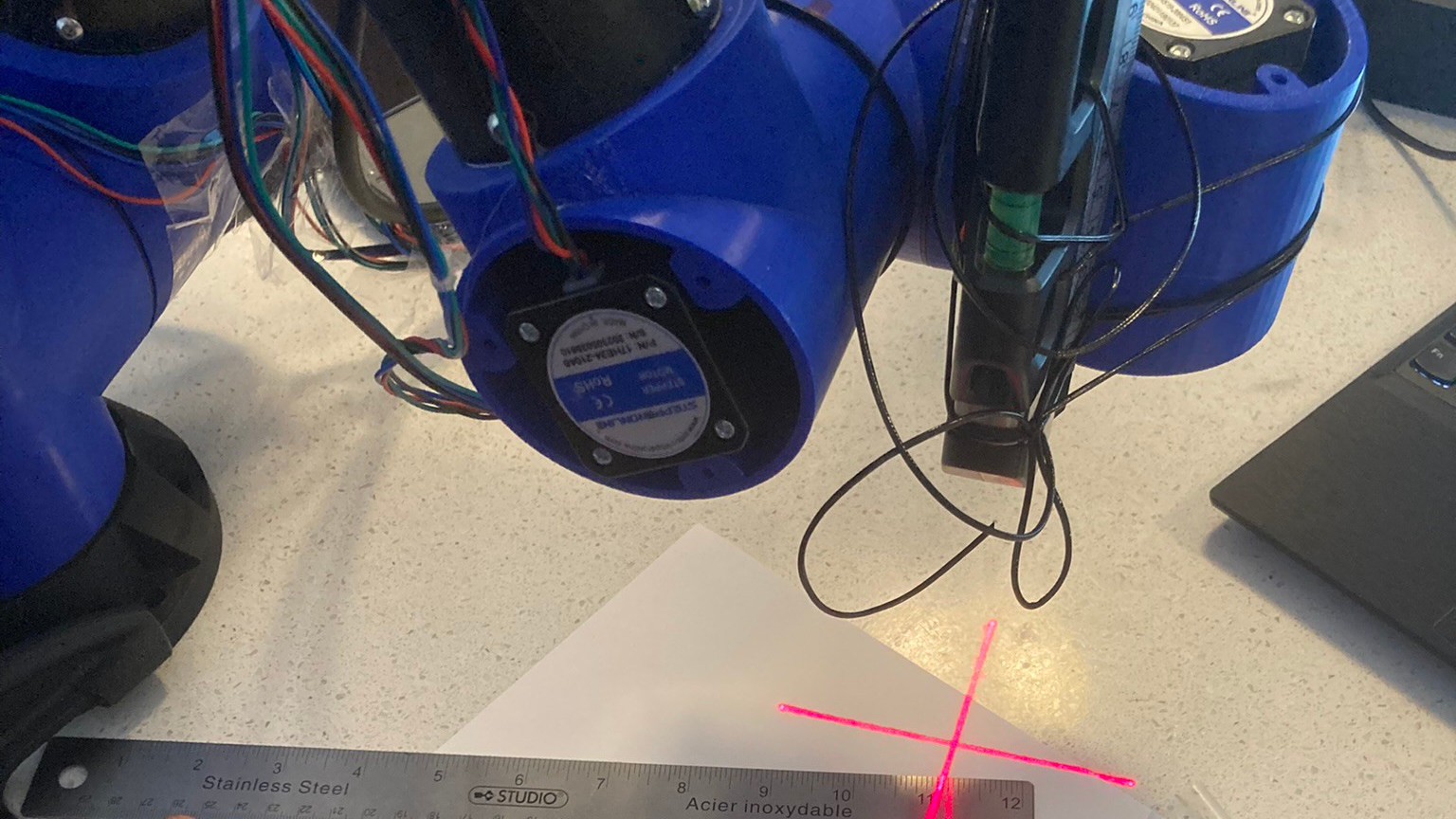
A 6DOF robotic arm looks simple from a distance: six joints, one end effector, and a job to do. Move closer, and the machine suddenly becomes a polite mechanical octopus with opinions. It must reach a target, avoid obstacles, respect joint limits, maintain orientation, stay stable, and not whack the workbench like an overcaffeinated intern. That is exactly why simulation and motion planning for a 6DOF robotic arm matter so much.
Before a robot arm welds a frame, picks a part, sorts electronics, paints a surface, or hands a tool to a human worker, engineers usually test the behavior in a virtual environment. Simulation lets teams build the arm, define joints, tune controllers, test trajectories, and catch mistakes before the physical robot becomes an expensive sculpture. Motion planning then gives the robot a safe, efficient path from “I am here” to “I need to be there,” preferably without drama.
In modern robotics, simulation tools such as Gazebo, NVIDIA Isaac Sim, MATLAB Robotics System Toolbox, RViz, and physics-based digital twins are often combined with planning frameworks such as MoveIt 2, OMPL, ROS 2 Control, inverse kinematics solvers, and collision-checking libraries. Together, they form a practical pipeline for developing reliable robotic manipulation systems. In other words, they are the difference between a robotic arm that gracefully assembles products and one that tries to high-five the nearest wall.
What Is a 6DOF Robotic Arm?
A 6DOF robotic arm is a manipulator with six degrees of freedom. In most industrial-style arms, those six freedoms come from six rotating joints. This structure allows the end effector to control position along three axes and orientation around three axes. That combination makes the robot suitable for tasks that require flexible positioning, such as pick-and-place, welding, inspection, assembly, dispensing, packaging, polishing, and machine tending.
Think of the six joints as a chain of decisions. The base joint turns the arm toward the work area. Shoulder and elbow joints extend or retract the reach. Wrist joints adjust the angle, roll, pitch, and yaw of the tool. With the right configuration, the robot can approach a part from above, from the side, or at a precise angle. With the wrong configuration, it may reach the same point but twist itself into a pose that looks like it lost a bet.
Why Six Degrees of Freedom Are So Useful
Six degrees of freedom are especially valuable because many real-world tasks require both position and orientation. A gripper does not merely need to reach a box; it must approach the box at the correct angle. A welding torch does not simply touch a seam; it must maintain a specific orientation, speed, and distance. A camera mounted on the wrist must point at the inspection target while avoiding collisions with fixtures, parts, and cables.
This is why 6DOF robotic arm simulation is not just a visual exercise. A pretty animation is nice, but a useful simulation must include kinematics, dynamics, collision geometry, joint limits, torque behavior, controller response, tool frames, and sometimes sensor feedback. The goal is not to make the robot look cool. The goal is to make sure it works when the real machine starts moving.
Why Simulation Comes Before Real Robot Motion
Running untested code on a real robotic arm is technically possible, in the same way it is technically possible to test whether a toaster floats. Simulation gives engineers a safer and cheaper way to validate ideas. A virtual model can crash, fail, oscillate, or miss a target without damaging hardware, stopping production, or giving the safety manager a new wrinkle.
In a simulation environment, developers can import or create a robot model, define the workspace, add obstacles, configure the end effector, and test motion plans. They can also replay trajectories, measure cycle time, inspect joint movement, tune velocity limits, and evaluate how the robot behaves near singularities. This process is especially useful for 6-axis robotic manipulators because small changes in tool orientation can create large changes in joint motion.
Core Benefits of Robotic Arm Simulation
Simulation reduces risk. It helps detect collisions before they happen in the physical cell. It shortens development time by allowing rapid testing. It supports training when hardware is unavailable. It enables digital twin workflows where the virtual system reflects the real workcell. It also makes debugging easier because engineers can pause, rewind, visualize frames, inspect transforms, and ask the robot, “Why are you like this?” without offending anyone.
For companies developing automation, simulation also improves communication. Mechanical engineers can review reachability. Software engineers can verify control logic. Process engineers can check task timing. Safety teams can evaluate restricted zones. Managers can see a demo before approving hardware purchases. Everyone gets a clearer picture, and fewer people have to stand around a robot cell pointing at a laptop.
The Building Blocks of a 6DOF Robotic Arm Simulation
A reliable simulation begins with an accurate robot description. In ROS-based workflows, this often means a URDF or Xacro model that defines links, joints, inertial properties, visual meshes, collision meshes, joint limits, and coordinate frames. The visual mesh makes the robot look correct. The collision mesh helps the planner understand what the robot might hit. The inertial properties influence dynamic simulation, especially when physics engines are involved.
For a 6DOF robotic arm, the model should define every joint clearly: joint type, axis of rotation, parent link, child link, origin, motion limits, velocity limits, and effort limits. Sloppy modeling here creates strange downstream behavior. A reversed axis can make the arm move backward. Missing collision geometry can let the planner drive through a table. Incorrect tool-frame placement can cause the gripper to miss the object by just enough to ruin your afternoon.
Kinematics: Forward and Inverse
Kinematics describes how the robot moves without focusing on forces. Forward kinematics calculates the end-effector pose from joint angles. Inverse kinematics does the opposite: it finds joint angles that place the end effector at a desired pose. For 6DOF arms, inverse kinematics is central to motion planning because most tasks are described in Cartesian space. The engineer says, “Place the tool here at this angle,” not “Set joint three to 47.2 degrees and hope for the best.”
Inverse kinematics can produce multiple valid solutions, especially for industrial arms with elbow-up and elbow-down configurations. A good planner must choose a solution that respects joint limits, avoids collisions, and supports smooth motion. In some cases, numerical IK solvers are used. In others, analytical IK solutions are created for specific robot geometries. Either way, IK is one of the most important pieces of the 6DOF robotic arm motion planning puzzle.
Dynamics and Controllers
Dynamics considers mass, inertia, gravity, torque, acceleration, and physical behavior. If kinematics is the map, dynamics is the reminder that motors, gears, and payloads are real. A trajectory may look perfect in a simple visualizer but fail when the robot must carry a heavy tool or stop quickly near a target. That is why physics-based simulation is useful for testing acceleration limits, controller tuning, payload behavior, and contact interactions.
Controllers translate planned trajectories into joint commands. In ROS 2 systems, controller frameworks can manage position, velocity, and effort interfaces. A common setup includes joint state broadcasters, joint trajectory controllers, and hardware interfaces. In simulation, these controllers are connected to virtual joints. On real hardware, they communicate with actual drives. The more closely the simulated controller behavior matches the physical system, the smoother the transition from simulation to deployment.
Motion Planning: Giving the Arm a Brain With Boundaries
Motion planning is the process of finding a path from a start state to a goal state while satisfying constraints. For a 6DOF robotic arm, the planner must consider joint limits, self-collision, environmental collision, tool orientation, workspace boundaries, velocity limits, acceleration limits, and sometimes task-specific rules. The best plan is not merely the shortest path. It is the path that is safe, smooth, executable, and appropriate for the task.
Motion planning usually involves several layers. First, the system identifies a target pose or joint configuration. Next, inverse kinematics may solve for possible goal states. Then the planner searches through the robot’s configuration space to find a collision-free path. After that, the trajectory is often smoothed, time-parameterized, and sent to a controller. Finally, the robot executes the motion while monitoring feedback.
Joint-Space Planning
Joint-space planning creates paths by moving from one set of joint angles to another. This approach is often efficient and predictable for point-to-point movement. It is useful when the exact tool path between two poses is not critical. For example, moving a robotic arm from a home position to a pre-grasp position can often be handled in joint space.
The downside is that the end effector may follow a curved or unintuitive path in Cartesian space. That may be fine when moving through open air, but it can be a problem for tasks like welding, cutting, gluing, scanning, or inserting parts. In those cases, Cartesian planning may be more appropriate.
Cartesian Path Planning
Cartesian path planning focuses on the path of the end effector through 3D space. This is useful when the tool must follow a line, arc, surface, or precise approach direction. A dispensing robot applying adhesive, for example, must follow the edge of a part smoothly. A robotic inspection camera may need to maintain a fixed distance from a surface while moving across it.
Cartesian planning can be more demanding because the system must continuously solve inverse kinematics along the path. It must also avoid singularities and joint-limit problems. A path that looks simple in tool space may require awkward joint motion. This is where simulation earns its coffee.
Popular Tools for 6DOF Robotic Arm Simulation and Planning
Modern robotics development often uses a stack of specialized tools instead of one magical software package. ROS 2 provides communication, modularity, and integration. MoveIt 2 provides manipulation planning, kinematics, collision checking, and planning scene management. OMPL supplies many sampling-based planning algorithms, including variants of RRT and PRM. Gazebo offers physics simulation and robot visualization. NVIDIA Isaac Sim supports high-fidelity simulation, synthetic data, and advanced robotics workflows. MATLAB and Simulink provide modeling, control design, inverse kinematics, collision checking, and code-generation workflows.
Each tool has strengths. Gazebo is widely used in ROS ecosystems and is excellent for open-source robotics development. MoveIt 2 is a powerful choice for robotic manipulation planning. Isaac Sim is attractive for high-performance simulation, perception-heavy workflows, and digital twin development. MATLAB is strong for algorithm design, prototyping, and engineering analysis. Many serious projects combine several of these tools rather than treating software like a winner-takes-all cage match.
MoveIt 2 and OMPL
MoveIt 2 is widely used for robotic manipulation in ROS 2. It helps configure planning groups, define end effectors, manage collision objects, solve kinematics, and generate trajectories. OMPL, the Open Motion Planning Library, is commonly used through MoveIt for sampling-based planning. Sampling-based planners are useful because high-dimensional robot configuration spaces are too complex to search with simple grid methods.
Algorithms such as RRT-Connect can quickly find feasible paths in many robotic arm scenarios. PRM-based planners can be useful when repeated planning queries happen in similar environments. RRT-star and related optimal planners may improve path quality, though often with higher computation cost. Choosing a planner is not about picking the fanciest acronym. It is about matching the planner to the workspace, obstacle layout, time requirements, and task constraints.
Gazebo and Physics-Based Testing
Gazebo is commonly used for simulating robot bodies, sensors, controllers, and environments. For a 6DOF robotic arm, Gazebo can show how joint controllers respond, how the robot interacts with gravity, and how the model behaves in a physics environment. It is useful for checking whether a URDF model is physically reasonable and whether controller parameters produce stable motion.
However, simulation accuracy depends on model quality. If collision meshes are too simple, contacts may be unrealistic. If inertial values are wrong, the arm may behave strangely. If friction is ignored, grasping tests may look better than real life. Good simulation is not magic; it is careful engineering wearing a graphics engine costume.
NVIDIA Isaac Sim and Digital Twins
NVIDIA Isaac Sim is increasingly used for robotics simulation, synthetic data generation, and high-fidelity virtual environments. It can be useful for testing robotic manipulation systems that combine motion planning with perception, cameras, sensors, and AI-based workflows. For teams building advanced automation, a digital twin in a physically based environment can help test workcell layouts, robot reach, sensor placement, and task logic before hardware arrives.
Isaac Sim is especially interesting when robot arms must interact with perception systems. For example, a simulated camera can detect parts, the motion planner can generate a trajectory, and the robot can execute the pick in a virtual cell. This type of workflow helps engineers test the full pipeline, not just the arm movement.
Collision Checking: The Robot’s Sense of Personal Space
Collision checking is one of the most important parts of motion planning. A 6DOF robotic arm must avoid obstacles in the environment and avoid colliding with itself. The planning scene typically includes the robot model, worktables, fixtures, bins, tools, parts, safety zones, and sometimes humans or mobile equipment. The planner evaluates whether a candidate state or path is valid before approving motion.
Collision geometry should be simplified enough for fast computation but accurate enough to represent real risk. Highly detailed CAD meshes may slow planning. Overly simple boxes may miss important protrusions. A smart workflow often uses simplified collision meshes for planning and more detailed visual meshes for display. The robot does not need to admire every screw head in the mesh; it just needs to avoid hitting the thing.
Planning Scene Accuracy
The planning scene must match the real environment. If the virtual table is five centimeters lower than the physical table, the robot may plan a path that looks safe but scrapes reality. If a fixture is missing from the simulation, the planner will happily route through it. If a tool changer is not included in the collision model, the arm may discover it the loud way.
For production systems, engineers should regularly verify calibration between the robot base, workcell fixtures, sensors, and tool frames. Accurate transforms are essential. A beautiful motion plan with a bad coordinate frame is just a very confident mistake.
Common Challenges in 6DOF Robotic Arm Motion Planning
One common challenge is singularity. A singularity occurs when the robot loses certain motion capabilities or requires extreme joint velocities to maintain tool movement. In practice, singularities can cause jerky motion, slowdowns, or planning failures. Simulation helps identify risky regions and adjust approach angles before the problem reaches hardware.
Another challenge is joint limits. A target pose may be reachable in theory but awkward in practice because one joint is near its limit. A planner may find a path, but the robot may have little room for adjustment. Good planning often includes margins around joint limits instead of treating the limits like a dare.
Collision complexity is also a major issue. A cluttered workspace with bins, fixtures, cables, and narrow gaps can make planning slow or unreliable. In these cases, engineers may add intermediate waypoints, define allowed collision pairs, simplify geometry, use task-specific constraints, or redesign the cell layout. Sometimes the best motion planning improvement is moving a bracket two inches to the left.
Practical Example: Pick-and-Place With a 6DOF Arm
Imagine a 6DOF robotic arm picking metal parts from a tray and placing them into a fixture. The simulation begins with a robot model, gripper model, tray, parts, fixture, and worktable. The engineer defines a home pose, a pre-pick pose above the part, a grasp pose, a retreat pose, a pre-place pose, and a final placement pose.
The planner first moves the arm from home to pre-pick. Then Cartesian motion lowers the gripper onto the part. After grasping, the arm retreats upward, plans a collision-free path to the fixture, approaches the placement point, releases the part, and returns to a safe position. During simulation, the engineer checks reachability, gripper clearance, collision margins, cycle time, and whether the wrist orientation creates awkward joint movement.
If the robot clips the tray wall in simulation, the fix may be simple: raise the retreat waypoint. If the arm approaches a singularity, adjust the tool angle. If planning fails near the fixture, simplify collision geometry or add a staged waypoint. This iterative process is normal. Robots rarely reward the first attempt, but they do reward patient debugging.
Best Practices for Simulation and Motion Planning
Start with an accurate robot model. Include realistic joint limits, tool frames, payload assumptions, and collision geometry. Use simplified meshes for planning and detailed meshes for visualization. Confirm coordinate frames early and often. A transform error can waste hours because everything looks almost right, which is the most annoying kind of wrong.
Test motion in layers. First verify forward kinematics. Then test inverse kinematics. Next check simple joint-space moves. After that, add obstacles and collision checking. Finally, test task-level sequences. This step-by-step method makes problems easier to isolate.
Use conservative limits in early testing. Reduce speed and acceleration until the trajectory is stable. Add safety margins around obstacles. Validate paths in simulation before execution. On real hardware, start slowly, use emergency stops, and keep humans outside the robot’s danger zone. The robot may be smart, but it does not have guilt.
Measure Planning Quality
A motion plan should be evaluated by more than whether it reaches the target. Useful metrics include planning success rate, computation time, path length, smoothness, minimum clearance, execution time, joint-limit margin, and repeatability. For industrial work, cycle time matters, but so does reliability. A slightly slower path that succeeds 99.9 percent of the time may be better than a fast path that fails whenever the part is placed slightly differently.
From Simulation to Real Hardware
The final test is transferring the planned behavior to a physical robotic arm. This step is often called sim-to-real deployment. The process requires calibration, controller validation, payload verification, safety checks, and gradual speed increases. Engineers should compare simulated joint trajectories with real execution data and adjust models when differences appear.
Common sim-to-real gaps include friction, backlash, flexible mounts, sensor noise, imperfect calibration, cable drag, inaccurate payload data, and contact behavior. A simulation can be excellent and still miss small real-world effects. The solution is not to abandon simulation. The solution is to improve the model, collect data, and treat simulation as part of a feedback loop.
Experience Notes: Lessons Learned From Working With 6DOF Robotic Arm Simulation
The first practical lesson is that the robot model is the foundation. If the URDF, joint axes, tool frame, or collision meshes are wrong, every later step becomes suspicious. Many beginners spend hours tuning planners when the real problem is a frame rotated 90 degrees or a tool center point defined in the wrong link. Always inspect the transform tree, visualize coordinate frames, and confirm that the end effector moves the way you expect.
The second lesson is to avoid testing everything at once. A full pick-and-place demo with perception, grasping, planning, collision objects, controllers, and physics may look impressive, but it is hard to debug. Build the system like a sandwich, one layer at a time. First make the robot appear correctly. Then move one joint. Then move all joints. Then plan to a pose. Then add obstacles. Then add the gripper. Then add perception. This method is less glamorous, but it saves sanity.
The third lesson is that collision objects must be treated seriously. It is tempting to add a few boxes and call the scene finished. In real applications, small objects matter. A clamp, cable bracket, tray lip, sensor mount, or tool flange can block an otherwise valid path. At the same time, overly detailed collision meshes can make planning slow. The art is creating collision models that are simple, conservative, and relevant.
The fourth lesson is that motion planning failures are not always software failures. Sometimes the workcell layout is poor. Sometimes the target pose is physically awkward. Sometimes the robot is too close, too far, or mounted at the wrong height. A good simulation can reveal these design issues early. When the planner struggles repeatedly, do not only blame the algorithm. Ask whether the task geometry makes sense.
The fifth lesson is to respect wrist orientation. With a 6DOF robotic arm, many targets are reachable, but not all reachable poses are comfortable. A wrist may flip unexpectedly, an elbow may swing near a fixture, or a joint may approach its limit. Adding intermediate waypoints and preferred joint configurations can make trajectories more predictable. For industrial tasks, predictability is often more valuable than mathematical elegance.
The sixth lesson is to compare simulated motion with real motion whenever possible. Record joint positions, velocities, execution times, and final pose accuracy. If the physical arm consistently deviates from simulation, update the model or controller settings. Simulation should not be a one-time drawing; it should evolve with the real robot cell.
The seventh lesson is simple: document your assumptions. Write down payload mass, tool center point, planner settings, controller limits, collision margins, coordinate frames, and calibration steps. Future you will be grateful. Future you may even buy past you a coffee. Robotics projects often fail not because the math is impossible, but because nobody remembers why a parameter was set to 0.037 at midnight six months ago.
Conclusion
Simulation and motion planning for a 6DOF robotic arm are essential for building safe, reliable, and efficient automation. Simulation allows engineers to test robot models, workcell layouts, controllers, sensors, and trajectories before risking hardware. Motion planning gives the robot the ability to move intelligently through complex spaces while respecting constraints.
Whether the workflow uses ROS 2, MoveIt 2, OMPL, Gazebo, Isaac Sim, MATLAB, or a custom industrial platform, the principles remain the same: model accurately, plan carefully, validate continuously, and never trust a path just because it looks smooth on screen. A 6DOF robotic arm is powerful because it can move with remarkable flexibility. The challenge is teaching it to use that flexibility wisely.
When done well, simulation becomes more than a development shortcut. It becomes a design tool, a safety tool, a training tool, and a bridge between imagination and production. And when the real robot finally performs the task smoothly, without collisions, hesitation, or surprise table-punching, the hours spent in simulation suddenly feel like the smartest investment in the room.
Note: This article is written for educational and engineering content purposes. Real robotic systems should always be tested with proper safety procedures, manufacturer documentation, risk assessment, and qualified supervision.