A bicycle odometer sounds like a simple gadget until you try to build one yourself. Then the project politely removes its helmet, rolls up its sleeves, and introduces you to magnets, interrupts, wheel circumference, battery management, debounce logic, and the tiny miracle of a microcontroller that can count wheel rotations while you are busy dodging potholes. That is where an ESP comes in. Whether you choose an ESP8266-based ESP-12 module or a newer ESP32 board, this small Wi-Fi-capable chip can turn an ordinary bike into a rolling data project.
The idea behind “An ESP Makes A Bicycle Odometer” is wonderfully practical: attach a magnet to a wheel spoke, mount a reed switch or Hall effect sensor near the fork, count every wheel rotation, and calculate speed and distance from those pulses. It is the same basic principle used by many traditional bicycle computers, but with one important difference: the ESP gives the project room to grow. Today it counts kilometers. Tomorrow it can log rides, blink LEDs, publish stats over Wi-Fi, display speed on an OLED screen, or quietly become the nerdiest part of your weekend ride.
Note: This article is original editorial content written for web publishing and based on established electronics, cycling-computer, and ESP development practices.
Why Build a Bicycle Odometer With an ESP?
You can buy a bicycle computer for the price of a modest lunch, so why build one? Because DIY electronics is not always about saving money. Sometimes it is about learning how measurement works, customizing the design, and enjoying the suspicious satisfaction of saying, “I made that,” while pointing at a small circuit board zip-tied to your bike.
An ESP-based bicycle odometer is a perfect beginner-to-intermediate maker project because it combines useful hardware with clear math. One wheel rotation equals one known distance: the wheel circumference. If the system knows the circumference and counts rotations, it can calculate total distance. If it measures the time between rotations, it can calculate speed. That is the core formula, and it is refreshingly honest. No cloud subscription. No mystery algorithm. Just a wheel doing wheel things.
The ESP8266 and ESP32 are especially attractive for this type of project. The ESP8266, often found in ESP-12 modules, is compact, inexpensive, and Wi-Fi enabled. The ESP32 adds more processing power, Bluetooth support, more pins, and better flexibility for advanced features. Both can be programmed in the Arduino environment, which makes the project approachable even if you are not the kind of person who reads microcontroller datasheets for bedtime comfort.
How the ESP Bicycle Odometer Works
The Magnet and Sensor Method
The most common DIY bicycle odometer design uses a magnet mounted on one wheel spoke. A sensor mounted on the fork detects the magnet every time it passes. This creates one electrical pulse per wheel revolution. The ESP reads that pulse and increments a counter.
A reed switch is a simple and affordable choice. It closes when exposed to a magnetic field, so when the spoke magnet passes by, the circuit briefly changes state. A Hall effect sensor performs a similar job electronically. It is often more durable because it has no tiny mechanical contacts inside. For a casual project, a reed switch works beautifully. For rougher riding, higher speeds, or long-term reliability, a Hall effect sensor is worth considering.
Counting Pulses With Interrupts
The magic ingredient is the interrupt. Instead of constantly asking, “Did the wheel turn yet? Did it turn now? How about now?” the ESP can run an interrupt routine whenever the sensor signal changes. This is like hiring a very alert assistant whose entire job is to tap you on the shoulder every time the magnet passes.
In Arduino-style code, the sensor pin can be attached to an interrupt using a function such as attachInterrupt(). The interrupt service routine should be short and quick. It can record the time of the pulse and increase a rotation count, while heavier calculations happen later in the main loop. This matters because long interrupt routines can create timing problems, and nobody wants a bicycle computer that loses its mind because it tried to do algebra at 18 mph.
The Basic Math: Speed, Distance, and Wheel Circumference
The odometer calculation starts with wheel circumference. If your tire rolls 2,100 millimeters in one full revolution, then 1,000 rotations equal 2,100,000 millimeters, or 2.1 kilometers. The ESP simply counts rotations and multiplies by circumference.
Speed is calculated from distance over time. If one rotation covers 2.1 meters and the time between pulses is 0.25 seconds, the bike is moving at 8.4 meters per second. Convert that into kilometers per hour by multiplying by 3.6, and you get about 30.2 km/h. That is fast enough to feel proud and slow enough that your road-bike friend may still pretend not to notice.
Accuracy depends heavily on wheel circumference. Tire size charts are useful, but the best method is the rollout test. Put the valve stem at the bottom, mark the floor, roll the bike forward one full wheel revolution in a straight line, and measure the distance between marks. Do this with the rider’s weight on the bike if you want better real-world accuracy, because tires compress under load. Pressure, tire model, rim width, and even surface can slightly change the effective rolling circumference.
Choosing the Hardware
ESP8266 ESP-12 Module
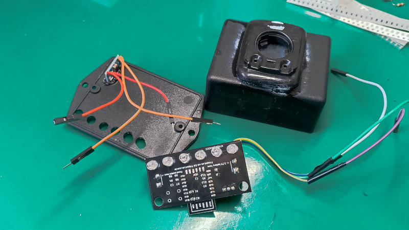
The ESP-12 is a compact ESP8266 module that suits a small bicycle odometer very well. It has enough GPIO pins for a reed switch input and a few indicator LEDs. A known example of this project style uses an ESP-12, a reed switch, a lithium battery, and six LEDs to show speed in 5 km/h increments. That kind of display is simple, rugged, and easy to read at a glance. It does not try to be a smartwatch. It just says, “You are moving, and here is roughly how enthusiastically.”
ESP32 Board
The ESP32 is better if you want a richer interface. It can drive an OLED screen, store ride data, use Bluetooth, connect to Wi-Fi, and handle more sensors. It is also a good choice if you plan to add cadence tracking, GPS comparison, a web dashboard, or smartphone syncing. The ESP32 is overqualified for counting a wheel magnet, which is exactly why makers like it. Overqualified microcontrollers are the golden retrievers of electronics: energetic, capable, and delighted to help.
Sensor Options
A reed switch is simple: connect one side to ground and the other to a GPIO pin with a pull-up resistor. When the magnet passes, the switch closes and pulls the pin low. A Hall effect sensor usually needs power, ground, and signal connections. It may provide cleaner switching and better longevity, especially when mounted securely and protected from weather.
Display Options
There are several ways to show speed and distance. A row of LEDs can indicate speed ranges. An OLED display can show exact speed, trip distance, total distance, battery level, and ride time. A phone-based dashboard can receive data over Wi-Fi or Bluetooth, though that adds software complexity. For a first build, LEDs or a small OLED are the sweet spot.
Designing the Circuit
A practical ESP bicycle odometer circuit includes the ESP module, a sensor input, a power source, and an output display. If using LEDs, each LED needs current limiting. If using an OLED, an I2C display keeps wiring tidy with only power, ground, SDA, and SCL lines. If using a raw ESP-12 module, remember that it requires proper boot configuration pins, a stable 3.3V supply, and a way to program it.
Power deserves special attention. A rechargeable 3.7V lithium battery is common, but the ESP needs regulated 3.3V. Many development boards include voltage regulators and USB charging circuits. These are convenient, though not always ultra-efficient. If battery life is a priority, choose low-quiescent-current regulators, avoid always-on LEDs, and put the ESP into sleep mode when the bike is idle.
Battery Life: The Real Boss Fight
Counting wheel rotations is easy. Keeping a battery-powered ESP alive for days or weeks is the harder challenge. Wi-Fi is useful, but it consumes power. A bicycle odometer does not need Wi-Fi every second, so the smart approach is to keep wireless features off during normal riding and enable them only for syncing or configuration.
ESP chips support sleep modes, including light sleep and deep sleep. Deep sleep can greatly reduce current draw, but it also changes how the program wakes and resumes. For an odometer, one strategy is to wake when movement begins, track the ride, save totals periodically, and return to sleep after several minutes of no wheel pulses. Another strategy is to keep the microcontroller awake during a ride but dim or disable the display when speed remains zero.
A practical build should also include a physical power switch. Yes, software sleep modes are elegant. But a switch is gloriously honest. It does not care about firmware bugs, Wi-Fi states, or whether you accidentally left the bike computer in “I am totally still awake” mode overnight.
Software Logic for a Reliable ESP Odometer
Debouncing the Sensor
Reed switches can bounce, meaning one wheel pass may produce multiple quick transitions. Without debounce logic, your odometer may think one rotation was two or three. Suddenly your relaxed ride to the coffee shop becomes a record-breaking mountain stage. Fun, but false.
Debounce can be handled in software by ignoring pulses that occur too soon after the previous valid pulse. For example, if your bike cannot physically complete another wheel rotation in less than 50 milliseconds, pulses inside that window can be discarded. The exact value depends on wheel size and maximum expected speed. Hall effect sensors may reduce bounce issues, but filtering is still a good habit.
Saving Distance Data
A useful odometer should remember total distance after power loss. On ESP32, the Preferences library can store small values in nonvolatile storage. On ESP8266, EEPROM emulation or flash-based storage can serve a similar role. The key is to avoid writing to flash too frequently because flash memory has limited write cycles. Save every set distance, every few minutes, or when the system detects inactivity instead of writing after every wheel rotation.
Handling Zero Speed
Speed should not stay frozen at your last moving value when you stop at a red light. The program needs a timeout. If no pulse arrives within a chosen period, the current speed becomes zero. This makes the display feel natural and prevents awkward bragging at stop signs.
Mounting the Odometer on a Real Bicycle
The electronics must survive vibration, sun, rain, dust, and the occasional dramatic lean against a garage wall. A 3D-printed enclosure, small project box, or sealed case can protect the ESP and battery. Use strain relief on wires, especially near the fork and sensor. Cable ties are acceptable, but do not let wires rub the tire, spokes, or brake components.
The magnet should be secured firmly to a spoke, and the sensor should be close enough to detect it reliably without touching. Test the spacing by spinning the wheel slowly and watching the serial monitor or display. If the system misses slow rotations, move the sensor closer. If it double-counts, check debounce logic, magnet orientation, and sensor stability.
Possible Features to Add Later
Once the basic odometer works, the project can grow in many directions. You can add trip distance, average speed, maximum speed, ride time, battery voltage, daily totals, or automatic data logging. With Wi-Fi, the ESP can host a small configuration page where you enter wheel circumference. With Bluetooth, it could send data to a phone. With an accelerometer, it could detect motion and wake automatically.
You can also make the display more creative. Six charlieplexed LEDs can show speed bands while using only three pins. An OLED can show a clean dashboard. A small e-paper display could save power and remain readable in sunlight. A buzzer could warn when speed passes a chosen threshold, although your riding friends may vote against that feature immediately.
Common Mistakes and How to Avoid Them
The first common mistake is using the wrong wheel circumference. A chart value may be close, but a measured rollout is better. The second mistake is skipping debounce logic. A bouncing reed switch can turn your odometer into a tiny fiction writer. The third mistake is saving data to flash too often. Store totals intelligently to protect memory.
Another mistake is leaving Wi-Fi active all the time. Wireless features are exciting, but they are expensive in battery terms. Use them only when needed. Finally, many builders underestimate mounting. A circuit that works perfectly on a desk may fail on a bicycle because bicycles shake, flex, and occasionally behave like shopping carts with ambition. Secure everything.
Why This Project Is a Great Learning Tool
An ESP bicycle odometer teaches the practical side of embedded systems. You learn interrupts, timing, sensor input, power management, nonvolatile storage, display output, and calibration. Better yet, the results are visible. You can ride around the block and immediately know whether your code behaves. That feedback loop is far more exciting than blinking an LED on a desk, although blinking LEDs still deserve respect for starting half the maker world’s careers.
The project also shows how simple measurements become useful when combined with thoughtful software. A wheel pulse is just a pulse. Add timing, calibration, storage, and display logic, and it becomes speed, distance, and ride history. That transformation is the heart of embedded design.
Experience Notes: What Building an ESP Bicycle Odometer Feels Like
The first experience most builders have with an ESP bicycle odometer is optimism. The wiring diagram looks easy. A magnet, a reed switch, a microcontroller, a battery, maybe a few LEDswhat could possibly go wrong? Then the first test happens, and the serial monitor starts reporting speeds that suggest the bicycle has entered low orbit. This is usually the moment when debounce stops being a boring word and becomes a personal mission.
Mounting the sensor is another lesson in humility. On a workbench, the reed switch triggers perfectly. On the bike, the magnet passes too far away, or the sensor bracket moves slightly, or the wire tugs just enough to make readings inconsistent. The fix is usually simple: reposition the sensor, secure the cable, and test at both slow and fast wheel speeds. Still, the process teaches an important rule of hardware: gravity, vibration, and weather are also part of the circuit.
Calibrating the wheel circumference is surprisingly satisfying. Marking the floor, rolling the bike forward, and measuring the distance feels almost old-fashioned, like tuning an instrument before a performance. It also makes the project feel real. The ESP is no longer counting abstract pulses. It is measuring your actual bike with your actual tire pressure on your actual floor, which may or may not be covered in garage dust and questionable life choices.
The display decision also shapes the experience. LEDs are wonderfully immediate. They do not give exact numbers, but they are readable at a glance and bring a retro arcade charm to the handlebars. An OLED feels more polished because it can show speed, trip distance, and battery level. However, it also invites the builder to add menus, icons, units, and tiny design decisions that somehow consume an entire Saturday. This is not a complaint. This is the hobby.
Battery testing is where theory meets patience. A project may run beautifully from USB, then behave differently on a lithium battery with a regulator. Sleep modes help, but they require testing. You may discover that a power LED on the board wastes more current than expected, or that the display remains awake when the ESP sleeps. These discoveries can be mildly annoying, but they also teach practical engineering better than any tutorial could.
The best moment comes during the first real ride. The wheel turns, the sensor clicks or switches, the ESP counts, and the display responds. It is a small thing, but it feels like the bicycle has learned to talk. Every rotation becomes data. Every street becomes a test track. Even a short ride becomes a debugging session with fresh air, which is much nicer than debugging under fluorescent lights while eating crackers over a keyboard.
In the end, an ESP bicycle odometer is more than a speed and distance meter. It is a compact lesson in making physical movement visible through code. It rewards careful measurement, clean wiring, sensible power choices, and a willingness to laugh when the first version claims you rode 42 miles in three minutes. Build it well, and it becomes a useful cycling accessory. Build it imperfectly, and it becomes an even better teacher.
Conclusion
An ESP makes a bicycle odometer because it combines the simplicity of wheel rotation counting with the flexibility of a modern microcontroller. A magnet and sensor provide the pulse. Wheel circumference gives the distance. Timing gives the speed. The ESP brings everything together with programmable logic, storage, display options, and potential wireless features.
For makers, cyclists, students, and electronics hobbyists, this project is practical without being dull. It is affordable, expandable, and full of useful lessons. Start simple with a reed switch, ESP-12, battery, and LEDs. Upgrade later with an ESP32, OLED display, Hall effect sensor, better enclosure, and ride logging. The road from “basic odometer” to “smart bike dashboard” is short, fun, and paved with tiny magnets.